|
|
Post by casias on Jun 4, 2016 11:47:59 GMT -5
Wiring. F$%^#g! wiring. Ok, so the wiring harness is on. It laid down really nice around the supercharger, and all of the connectors are high quality and placed in the right place. I had to oblong the holes on the coil packs to move them out about 3/4 inch. Also had to cut off a stupid grounding stud that was on the firewall, and wouldn't let the wiring harness slide past. Otherwise, pretty uneventful. TR6 spark plugs installed 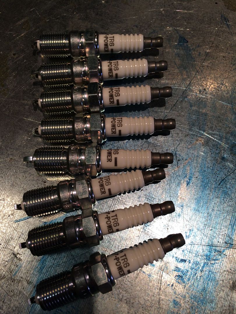 Stupid stud right against the passenger cylinder head. The wiring harness had to lay behind the cylinder head so the lead to the transmission would reach. Wasn't a great location to try to use an angle grinder, but I got it done. 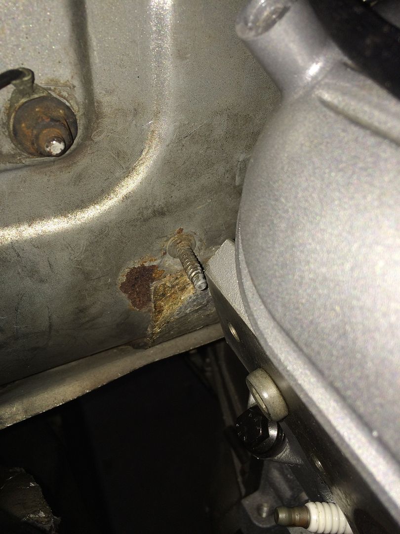 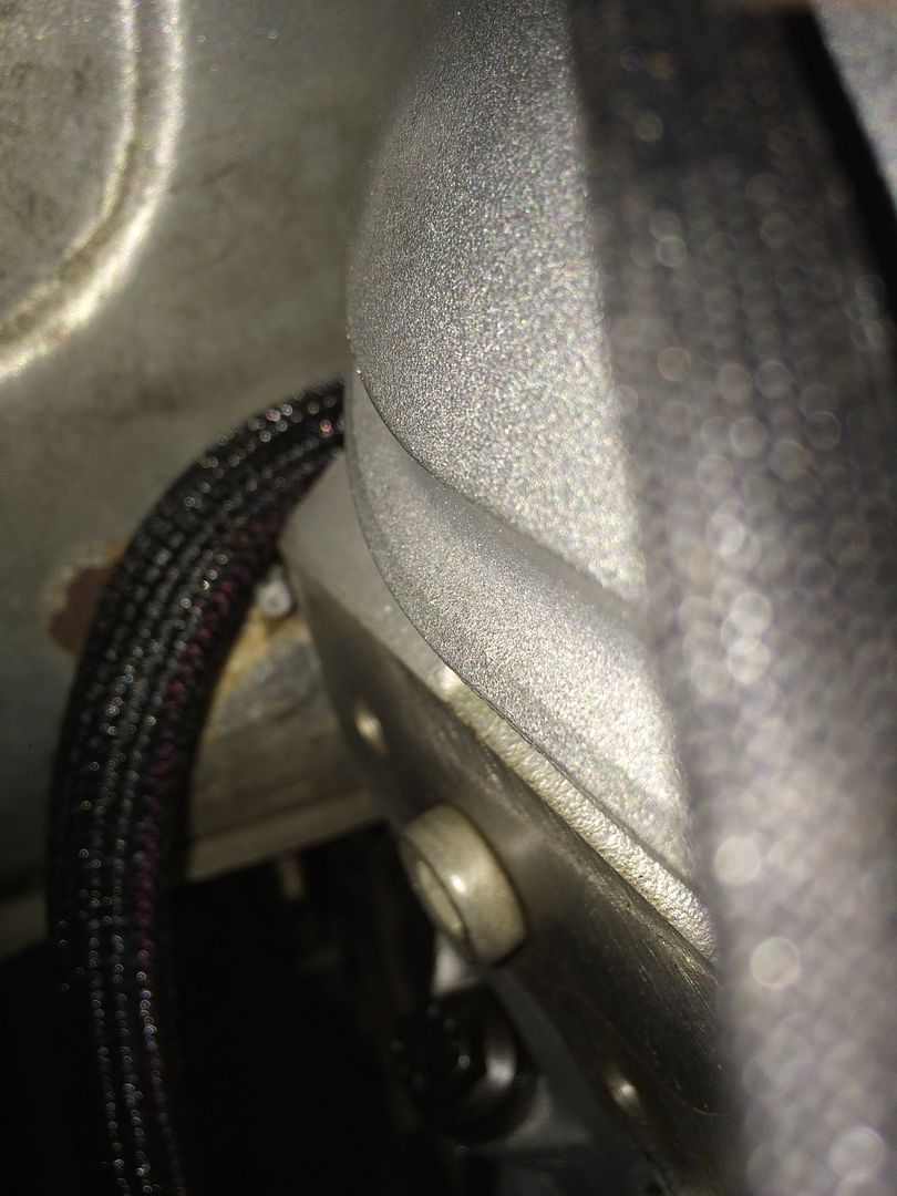 Wiring, coil packs, headers, fuel rail. All is on now. 3 views of the finished top end. 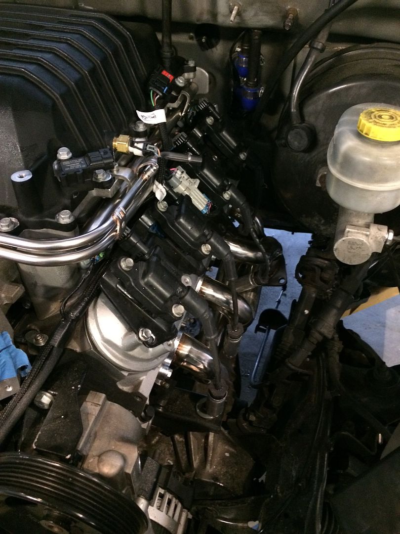 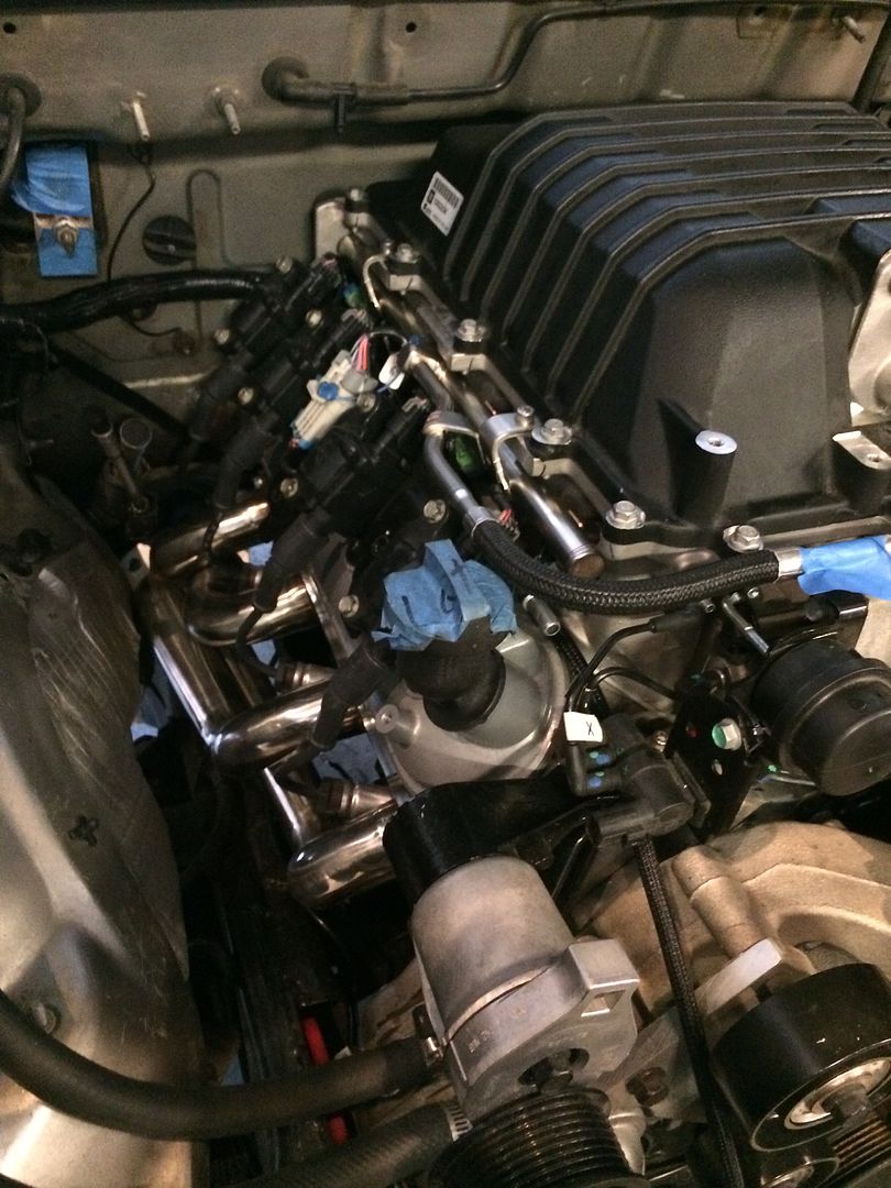 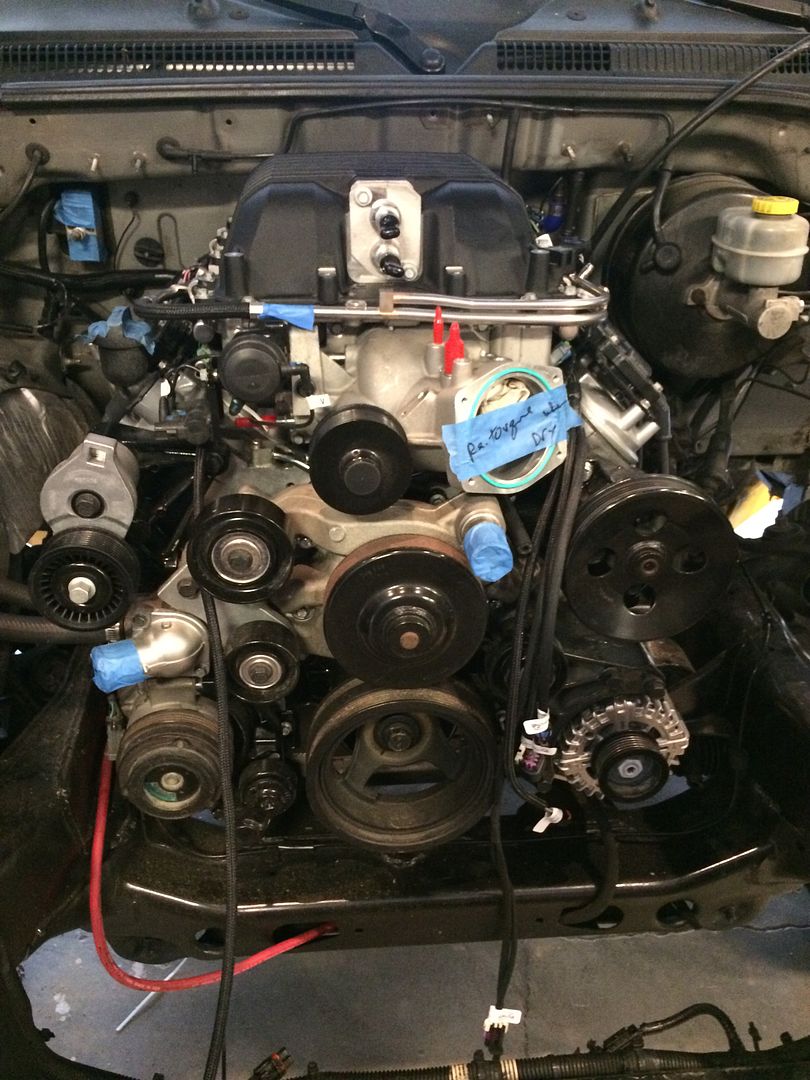 |
|
|
|
Post by casias on Jun 6, 2016 17:39:47 GMT -5
Ok, bear with me. These pictures are very close up, and kind of hard to follow. I have had a ton of questions about shift linkage. The 6l80/90 transmission has the shift cable connecting from the rear of the transmission forward. The cable is really, really long. I used a Silverado cable for the LS DAK, but it was a pain to get under the dash and replace it, and then run it under the carpet, under the truck and wrap it all the way around to the bracket. This time, I want to use the original Durango cable, with linkage to connect it to the transmission. It will have to reverse the direction of the shift, but I have plans for that. Today, I wanted to get the original Durango bracket firmly mounted to the 6l80 transmission. Here is how I did it. Diving into my junk drawer, I pulled out an Umbro curtain rod bracket. If you think this is a recurring theme, it is because we had 12 windows in the house that got new curtains when we bought it. So I have a lot of these brackets. I cut it down to just the angled end, so I could attach it to the bottom bolt on the transmission bell housing. 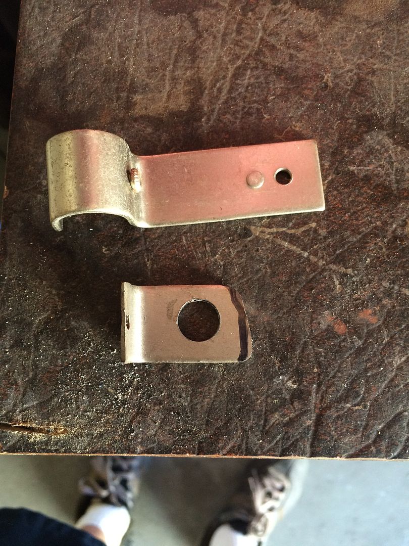 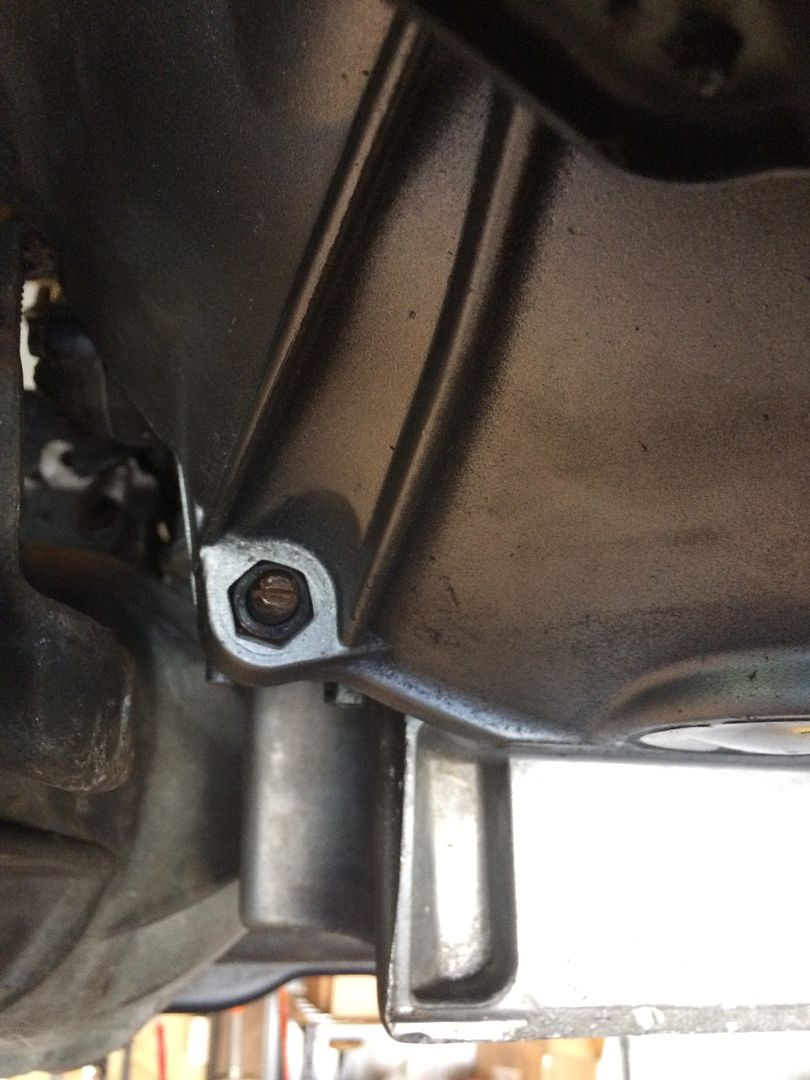 Here is the original Dodge bracket, as it started. The angle bracket I made from the curtain rod bracket is on the lower bolt of the transmission. 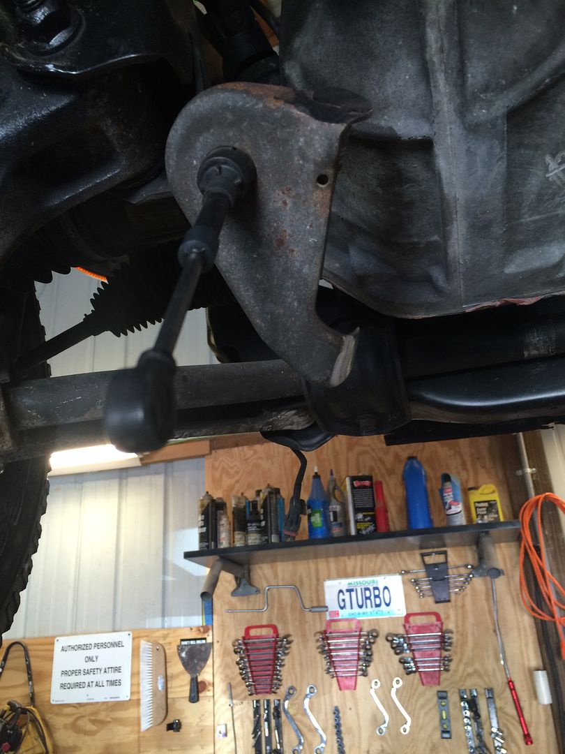 I drilled out this flat area on the upper drivers side of the 6l80 transmission. I think it is a pry-point to separate the transmission from the engine. Now it will hold my new bracket. 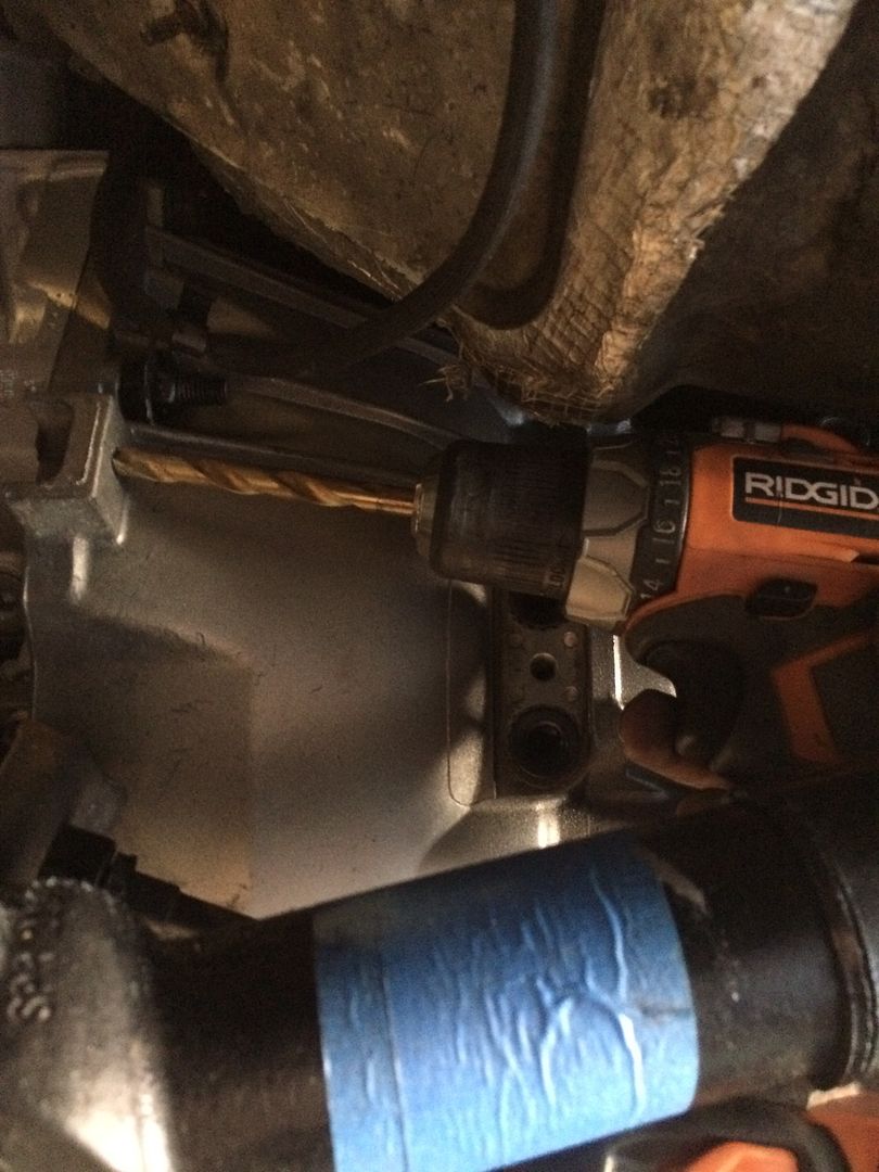 Looking up from the bottom, towards the engine bay. Transmission pan is on the right, and front driveshaft is on the left. 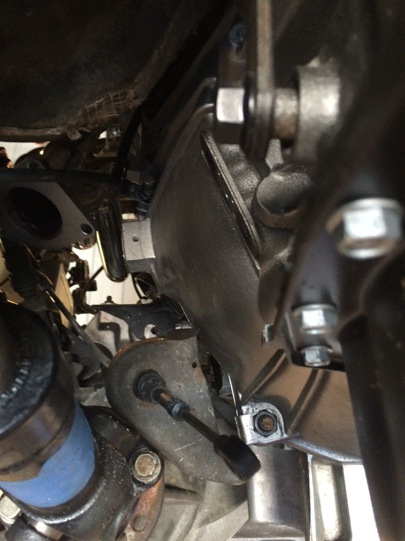 There wasn't enough room to get a t-type tap handle in to thread the hole I made in the transmission, so I had to make another tool. take the handle off of the tap handle, weld a nut on the end, and use my drill to tap the threads. 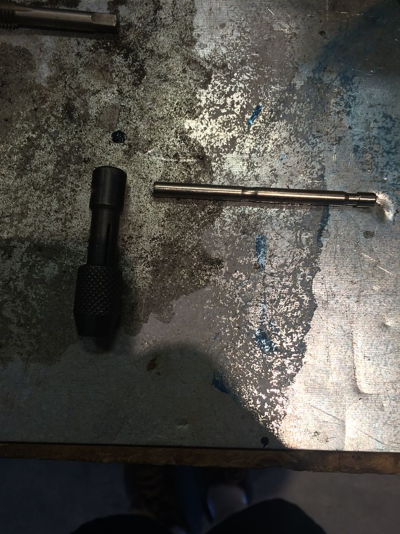 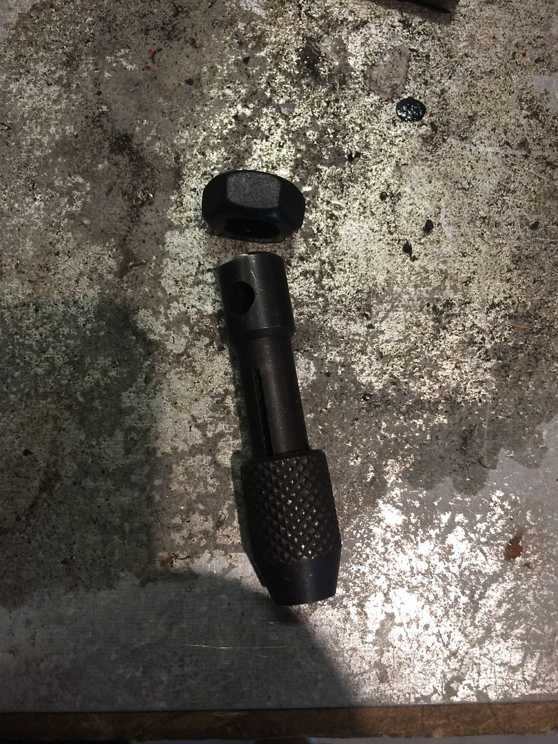 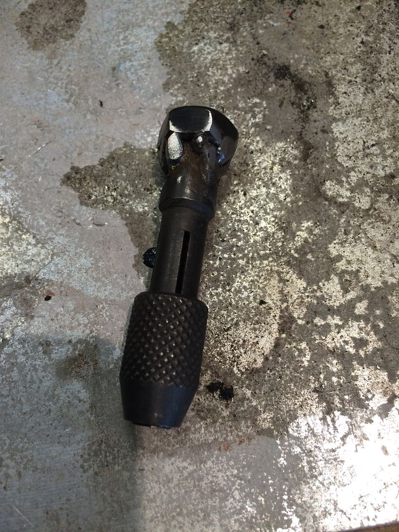 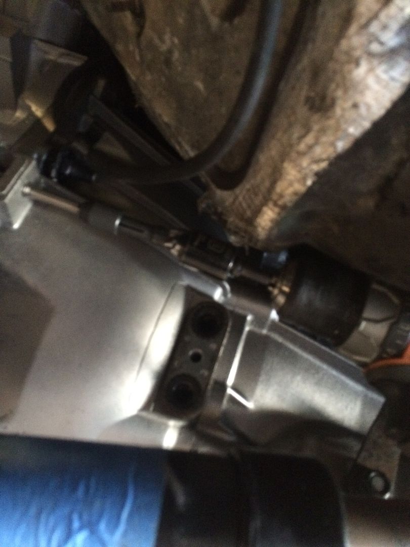 New hole, tapped for M10X1.5 bolt. 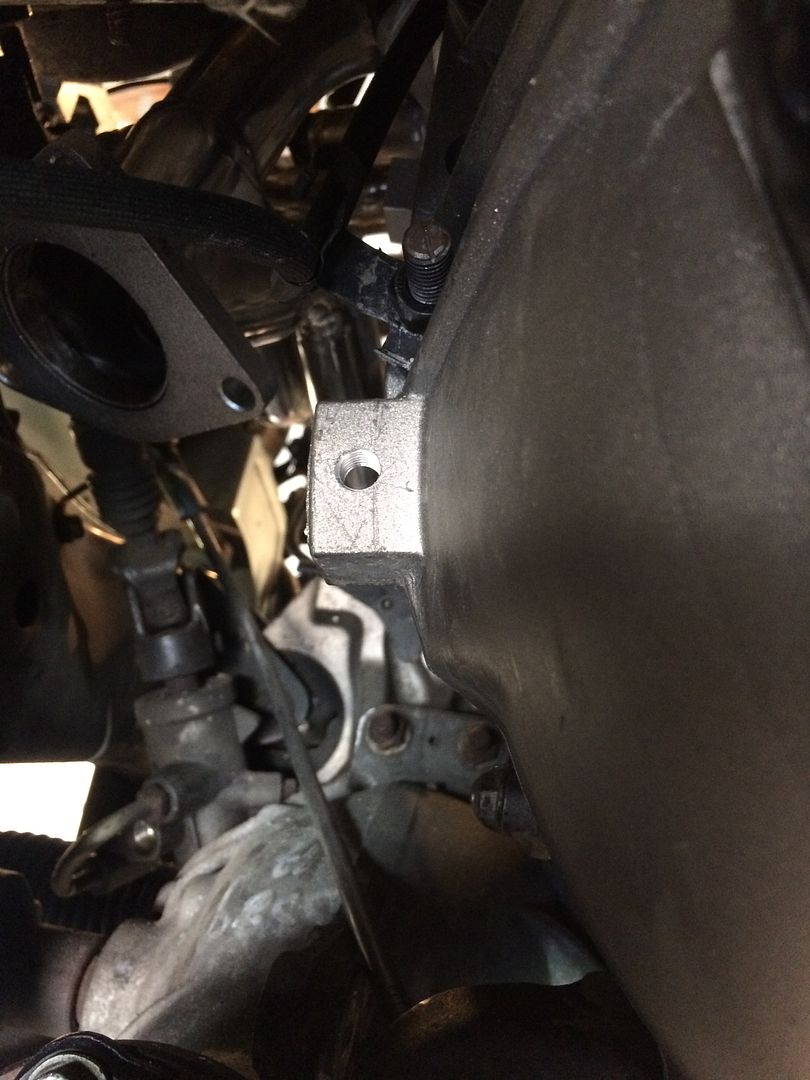 Now I found a rusty exhaust hanger from something. It was in the back of one of my trucks. 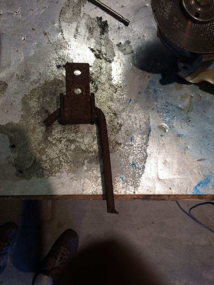 Attached to the new hole, it locates the top of the original Dodge bracket. the bottom hole has the curtain rod angle piece to locate the bottom of the bracket. A little welding, a little paint. Now the cable is firmly secured to the transmission. 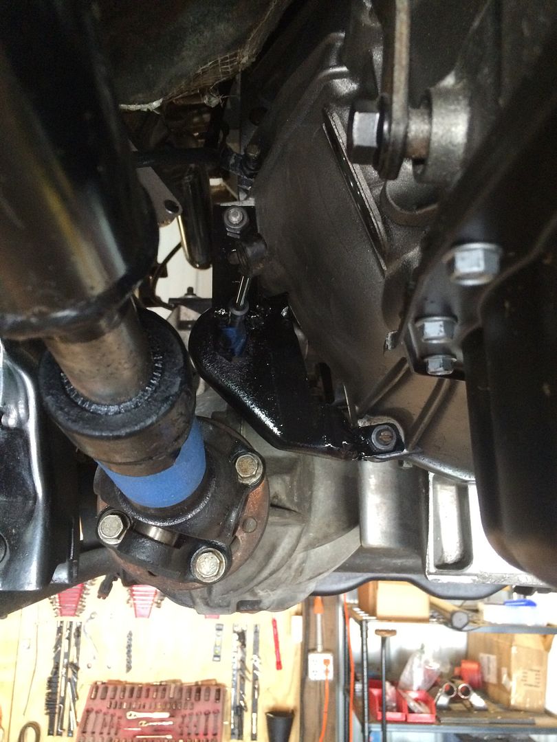 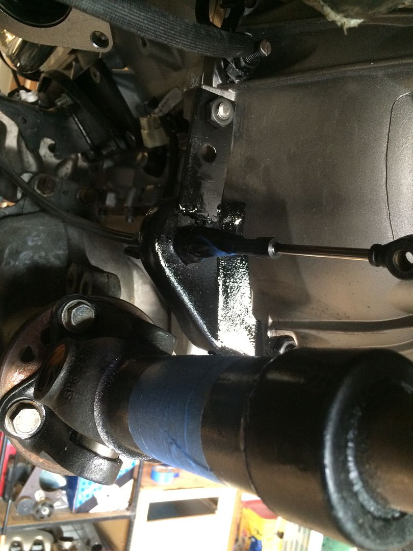 Remember the other end of that exhaust hanger? I needed to lengthen the transfer case linkage by about 1 1/2 inches, to it went to use on that. 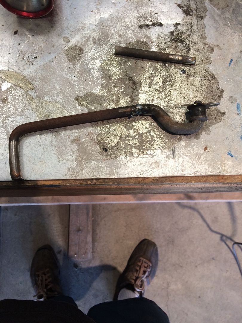 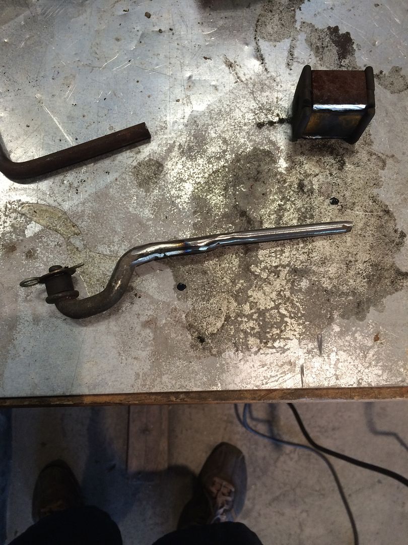 |
|
|
|
Post by casias on Jun 12, 2016 9:41:14 GMT -5
Problem. The front axle is supported by a heavy cast iron bracket that attached to the Dodge 46re transmission bell housing. When the transmission went away, so did the bracket. This left the front axle with nothing to stop it from rotating under load. Here are more close-up pictures of how I fixed this. It's really hard to get good shots under there, but anyone who has worked on one of these will know what they are looking at. Original cast iron bracket on the bottom of the old 46re transmission 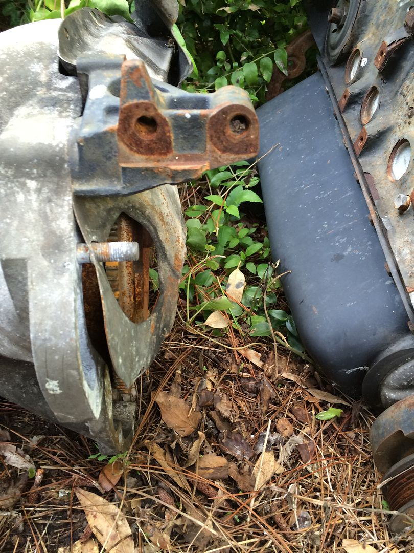 3/8 steel plate attached with 10 mm bolts to the top of the front axle. 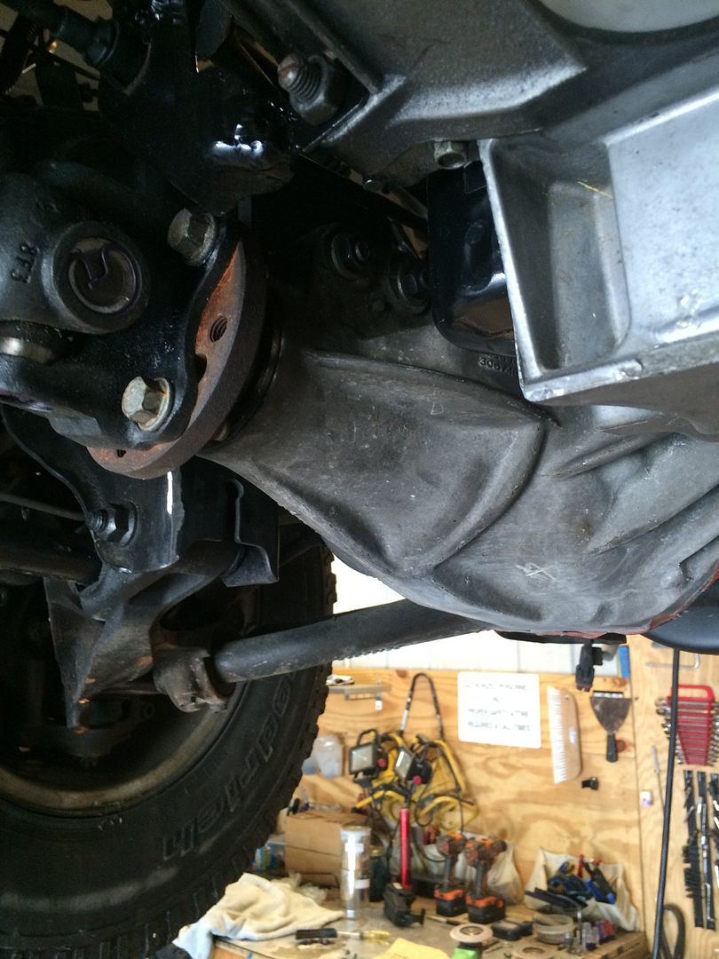 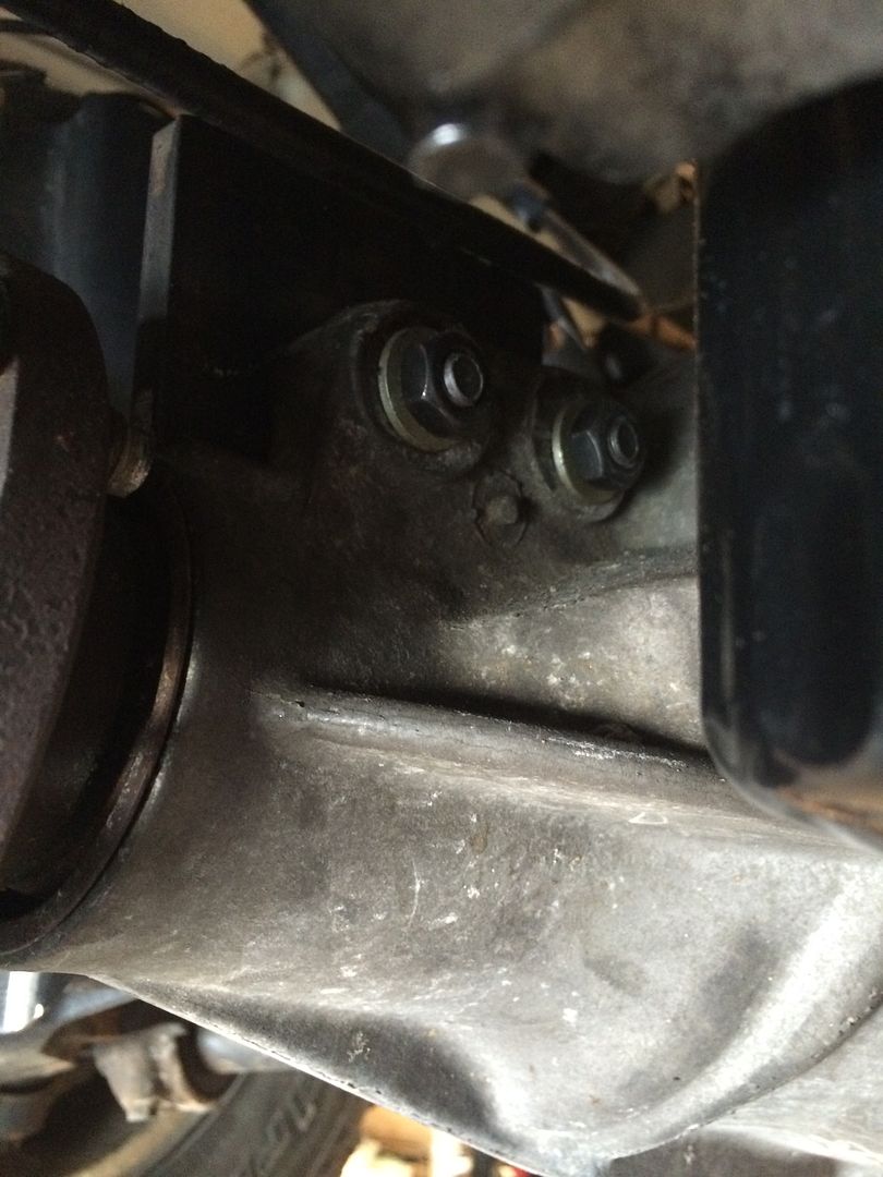 1.5 X 0.120 wall DOM tubing welded to plate. My 120v MIG welder really goobered thsi up. It just doesn't have enough oomph, even with 3 passes. Looks like crap, but it is solid. 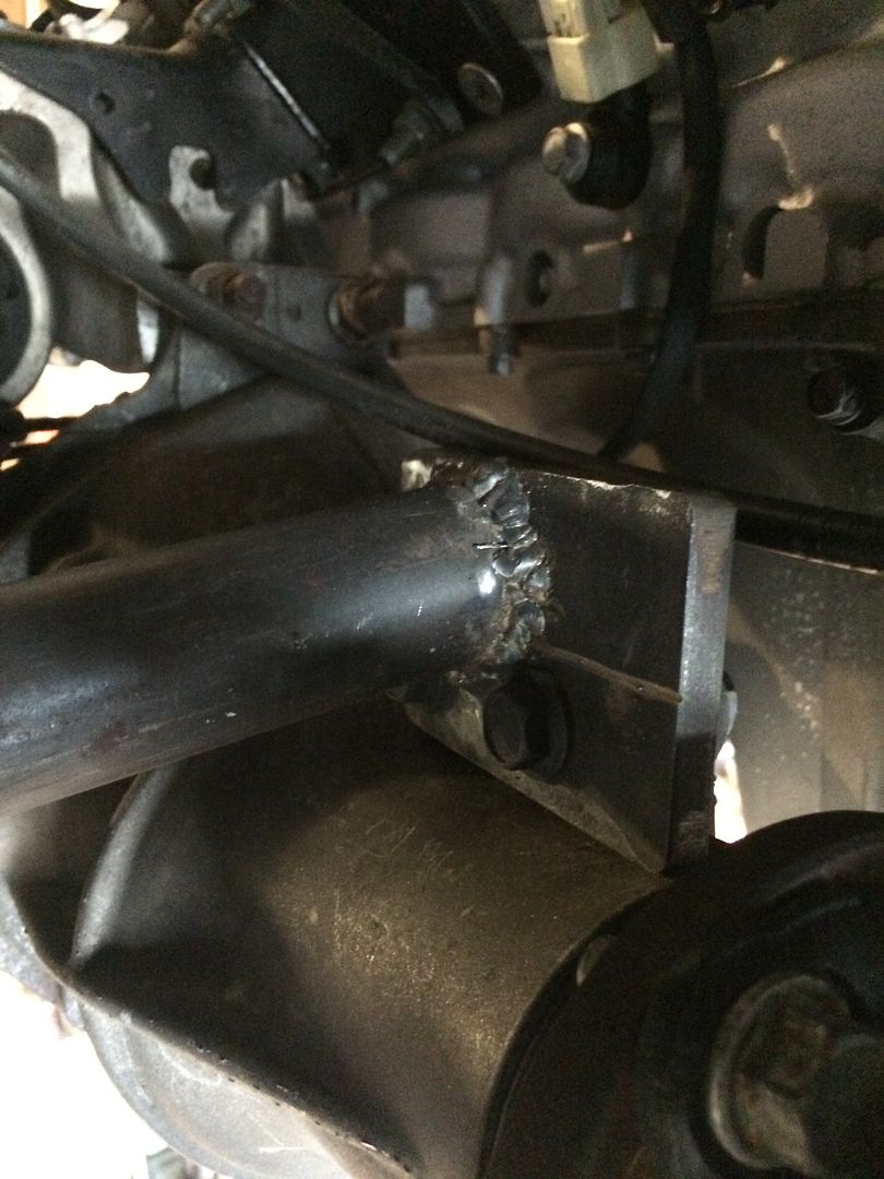 Other end of tubing welded to frame. Again, the MIG just wasn't up to the task. So I ground it down and found the weld so-so. 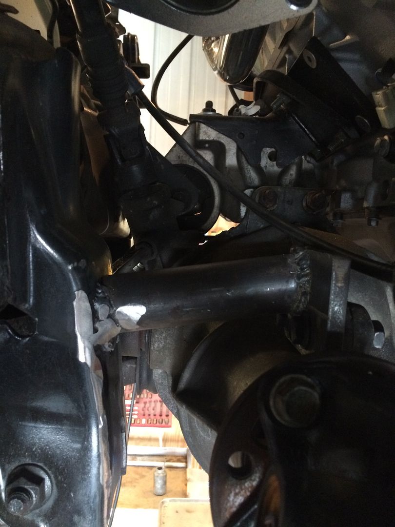 My welder. It's small, and does most of the jobs I need, but just didn't work for this one. 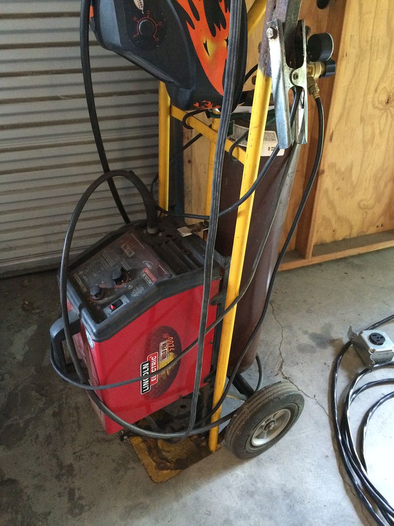 So out comes the stick welder. This is a 220v DC stick welder, which has bailed me out numerous times. Stick welding has a ton of benefits that I often forget about. Ability to reach way into somewhere a MIG gun can't get to, clean welds through not so clean steel, ease of use. This little Everlast was about $330 (?) at the depot a couple of years ago. 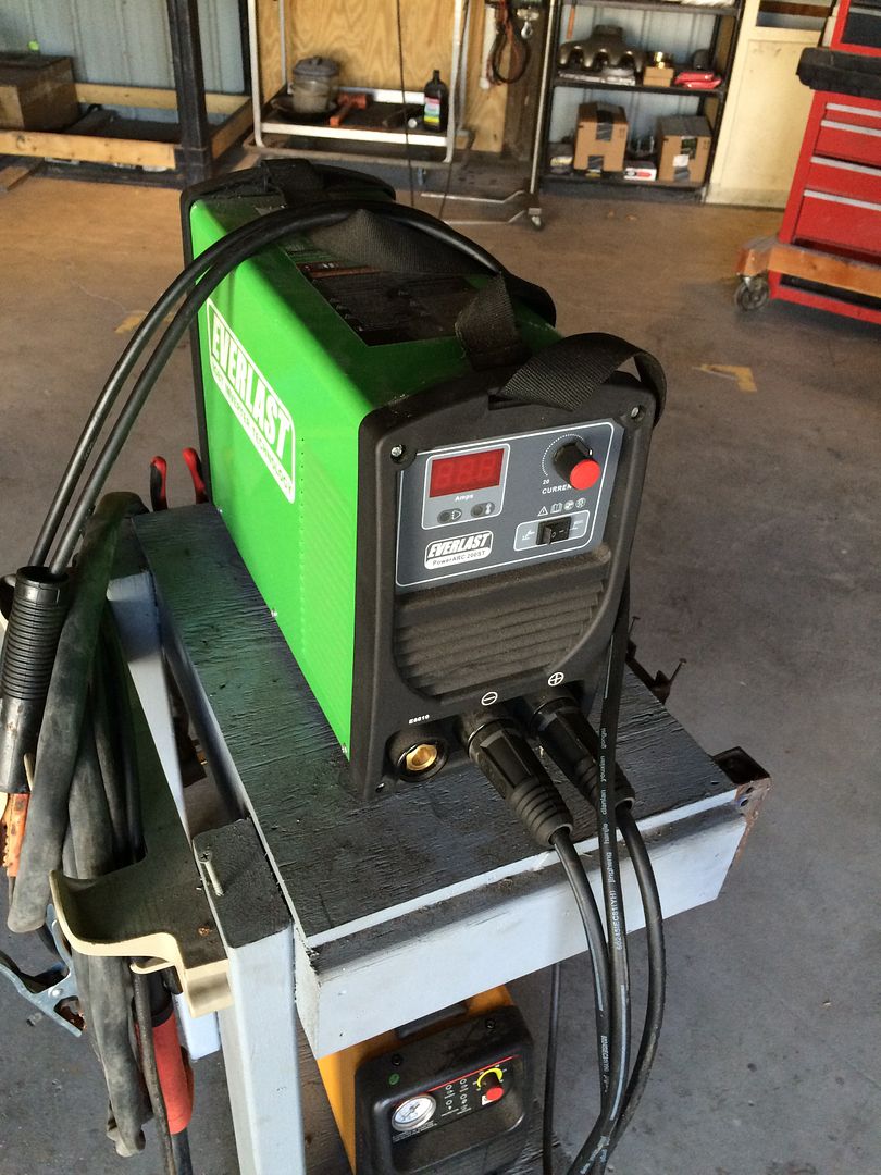 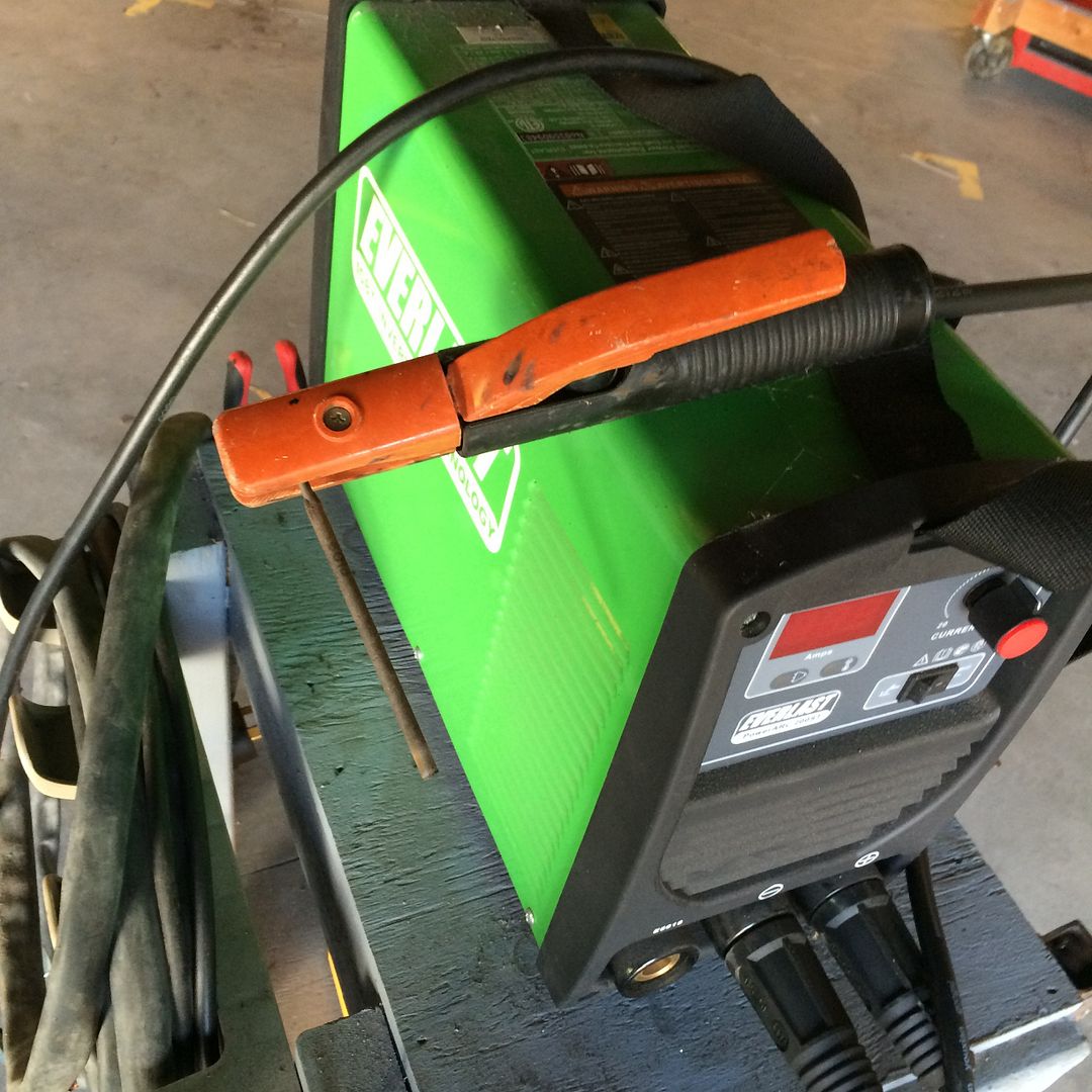 Ground down the weld and started over with the stick welder. Much better. 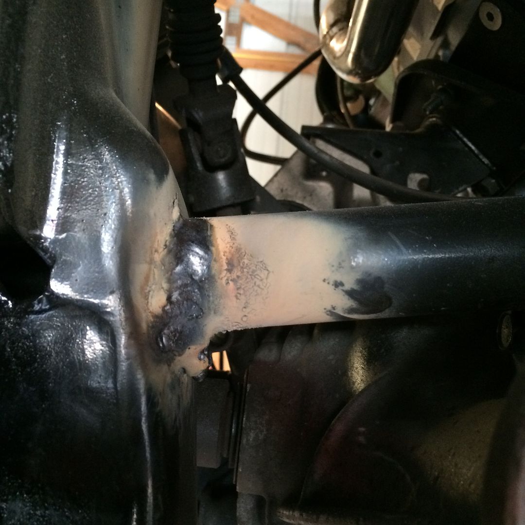 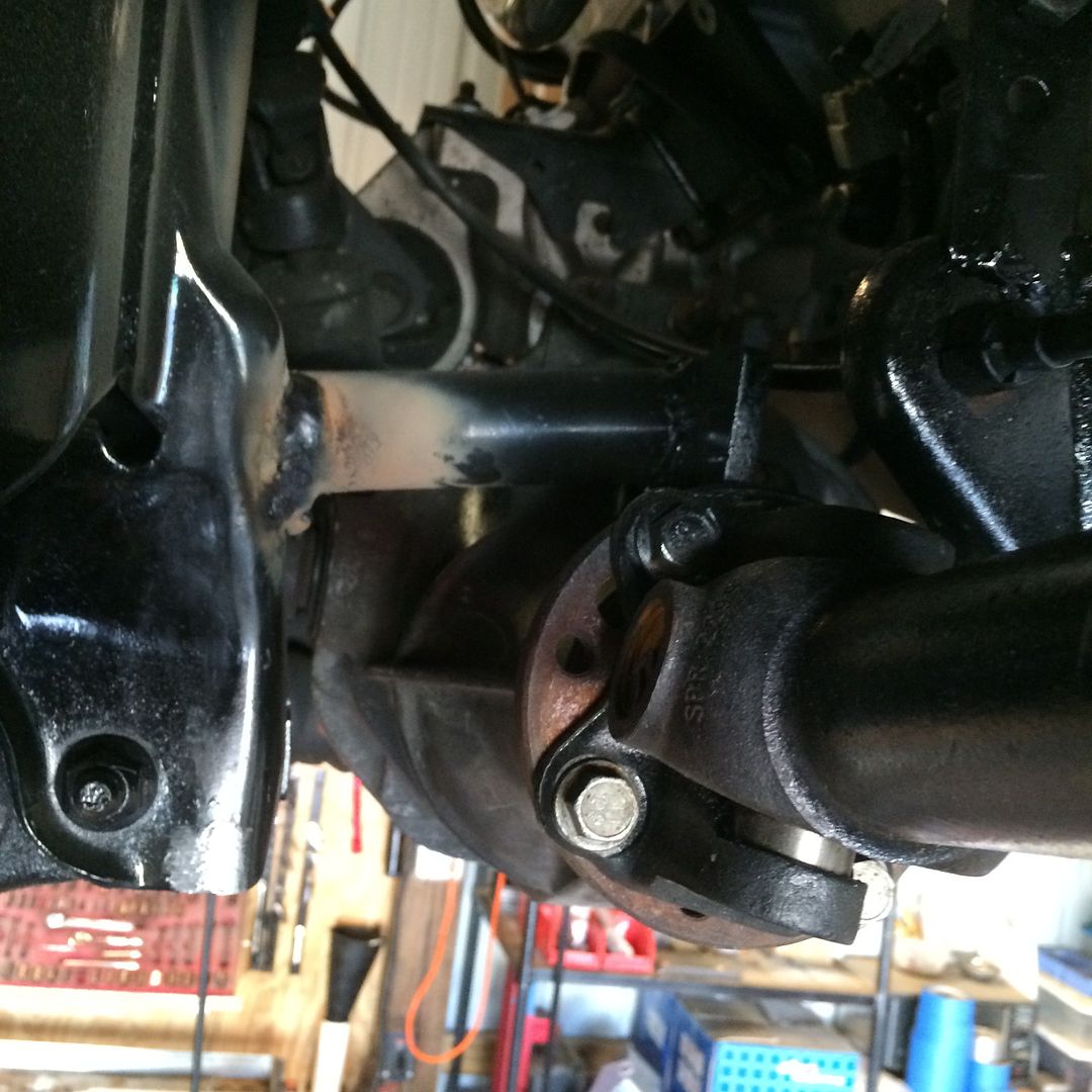 |
|
|
|
Post by casias on Jun 14, 2016 6:31:59 GMT -5
Transmission linkage. This is a very common question that I get. Every build is going to be different because of the differences between the truck (Durango/Dakota 2WD/4WD 46re or other transmission), and the chosen transmission (4l60, 4l80, 6l90). The basic plan for transmission linkage, in my opinion, is as follows: 1) Try to avoid changing the original shift cable. The main reason for this is that I hate crawling under the dash. Period. There is an adjustment on the transmission selector that moves the pointer. On the LSDAK truck, I have it pretty close, but it's not perfect. 2) Establish a firm point for the transmission end of the cable. This has to be much more stout than you would think. If it begins to deflect, it will be hard to get the trans in the correct gear. 3) Conversion from shift cable to transmission lever. In my opinion, this is easiest done with welding. Using the parts you have, and adding or removing length seems to be the best way to go. Here is how I did the Durango. I know some of this is duplicate, but I am going to post this again as its own thread. Original Dodge cable and bracket on the Durango. This is typical of the 46re mounting bracket for 2wd and 4wd.  Locate a place to mount it. On my 6l80 transmission, I used this flat whatever it is to drill and tap for M10 bolt.  \    Attach the bracket at one more point. I used leftover exhaust hanger to attach the top of the bracket to the hole I created. The other end was attached to the bottom bolt on the transmission bell housing.Cardboard templates come in handy here, so you can cut pieces to fit. Creativity is key.  Here, you can see the top of the bracket with a the exhaust hanger welded on, attached to the top hole that I made using a M10 bolt. The bottom has a tab welded on, and is attached to the bottom driver's side bolt on the transmission bell housing.   Original shift lever on the 6l80, flipped over (And the link ball, whatever you call it, has been ground off). Man I love new GM stuff. A reversible shift lever. How easy is that? No place to mount the cable though. A boss would have been nice. 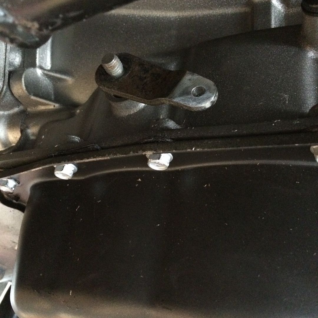 Parts are assembled. I have the shift lever from the 6l80 with the attachment ball ground off, leftover piece of exhaust hanger with the rubber mount removed, leftover T handle from the tap I converted for use in my drill (see post above), and the kick-down lever from the 46re transmission. 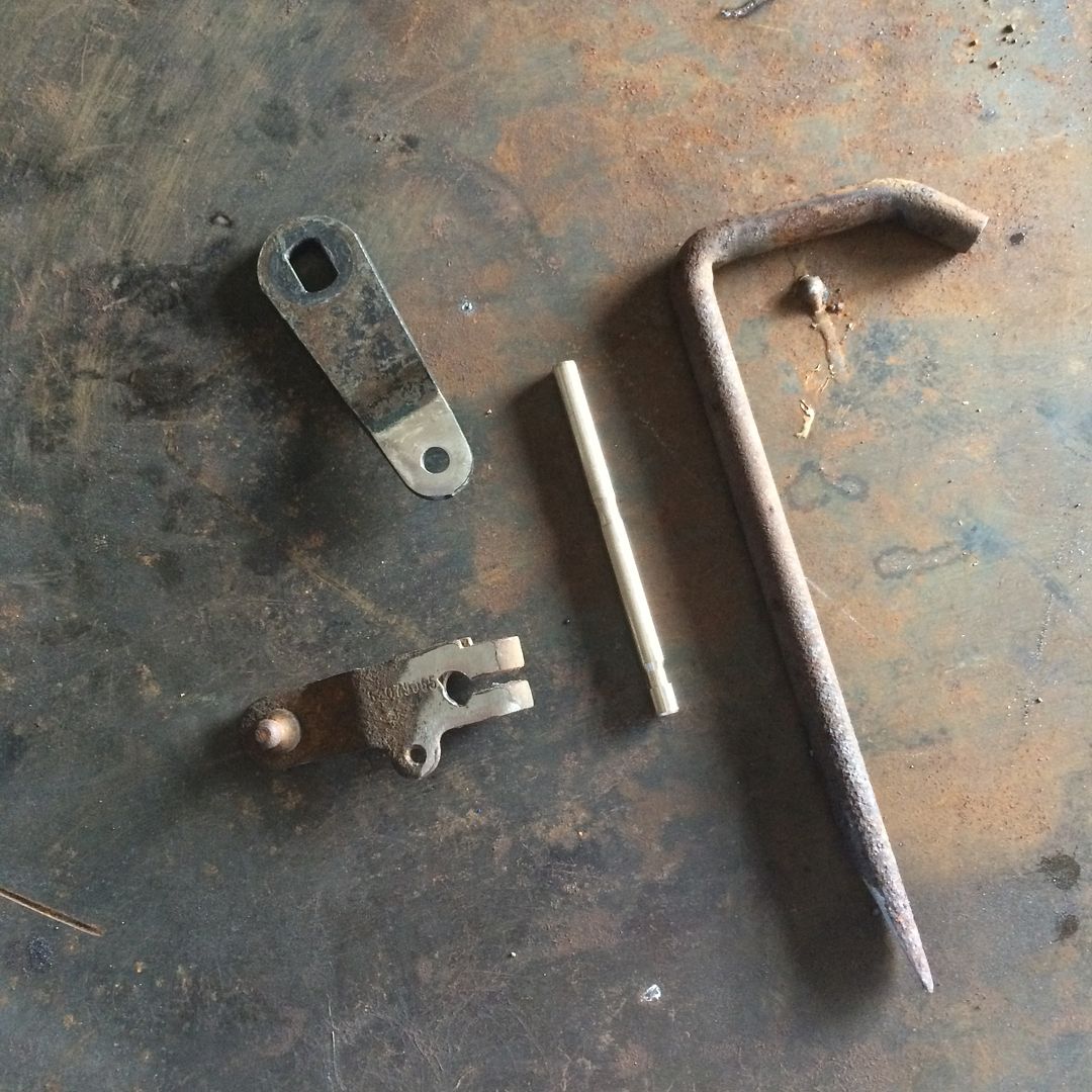 GM lever attached to kick-down lever, using the T handle as a pin. This is spot welded on both sides, and cut off flush, allowing these two pieces to pivot. 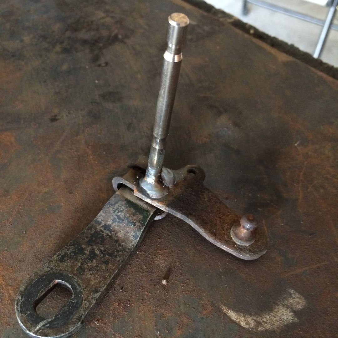 Exhaust hanger rod used as extension, welded on with front half of old shift linkage from 46re welded to the front. This way, I know the attachment ball matches the cable. Easy. 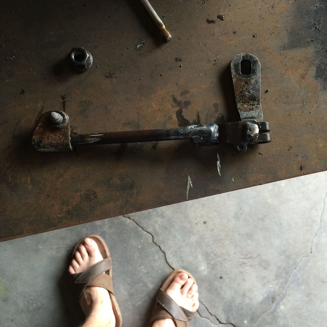 When I fit it up, I realized that the shift linkage needed something to bump on when it was extended past drive. Otherwise, it would flip up on itself. Back to my massive supply of Umbro curtain rod brackets. Along with a 6 mm stainless bolt with the head cut off, a nut that is larger than the 6 mm bolt to act as a spacer, and a 6mm nyloc nut. Followed by a bunch of pictures. 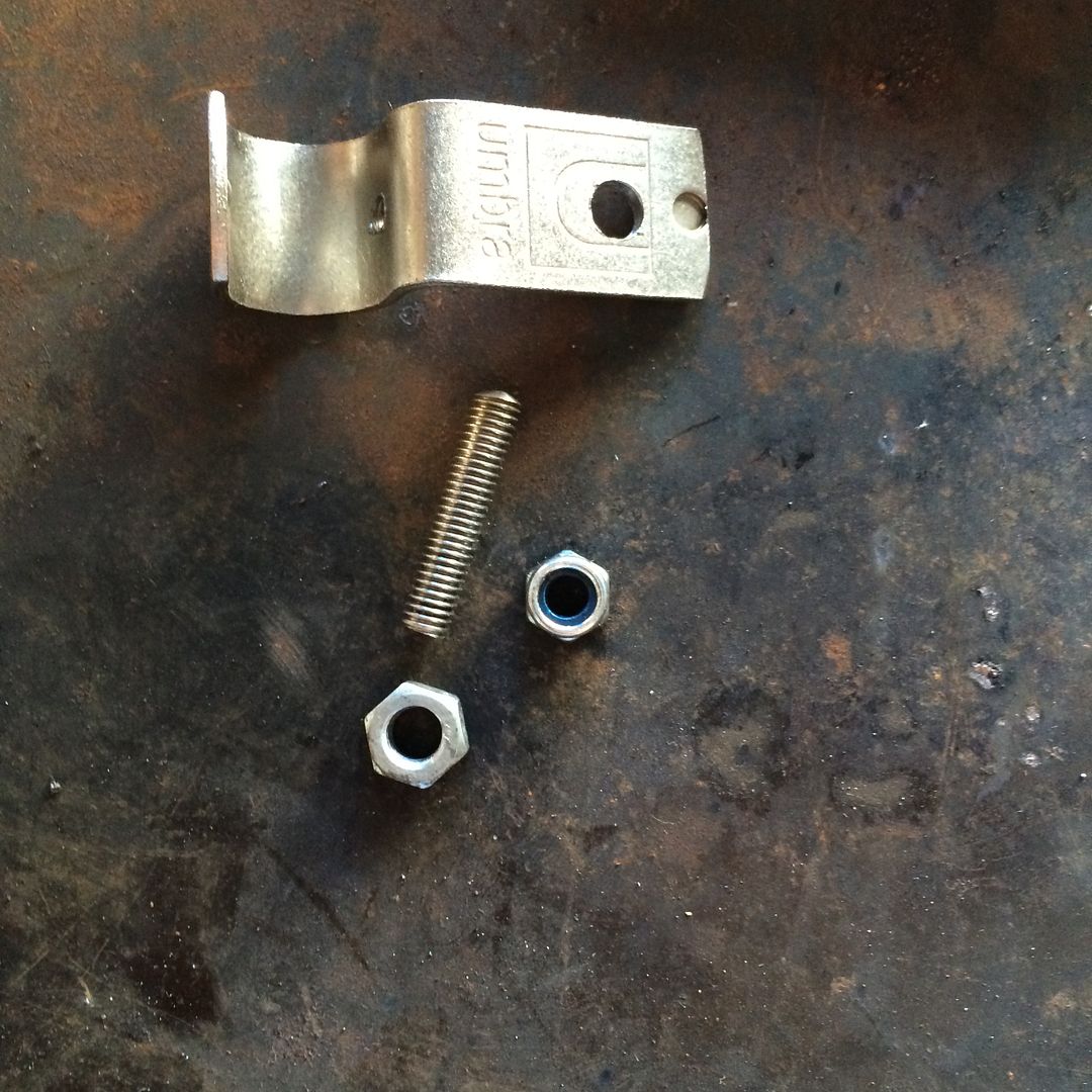 Stud threaded in. Nut as spacer. linkage installed in final position. 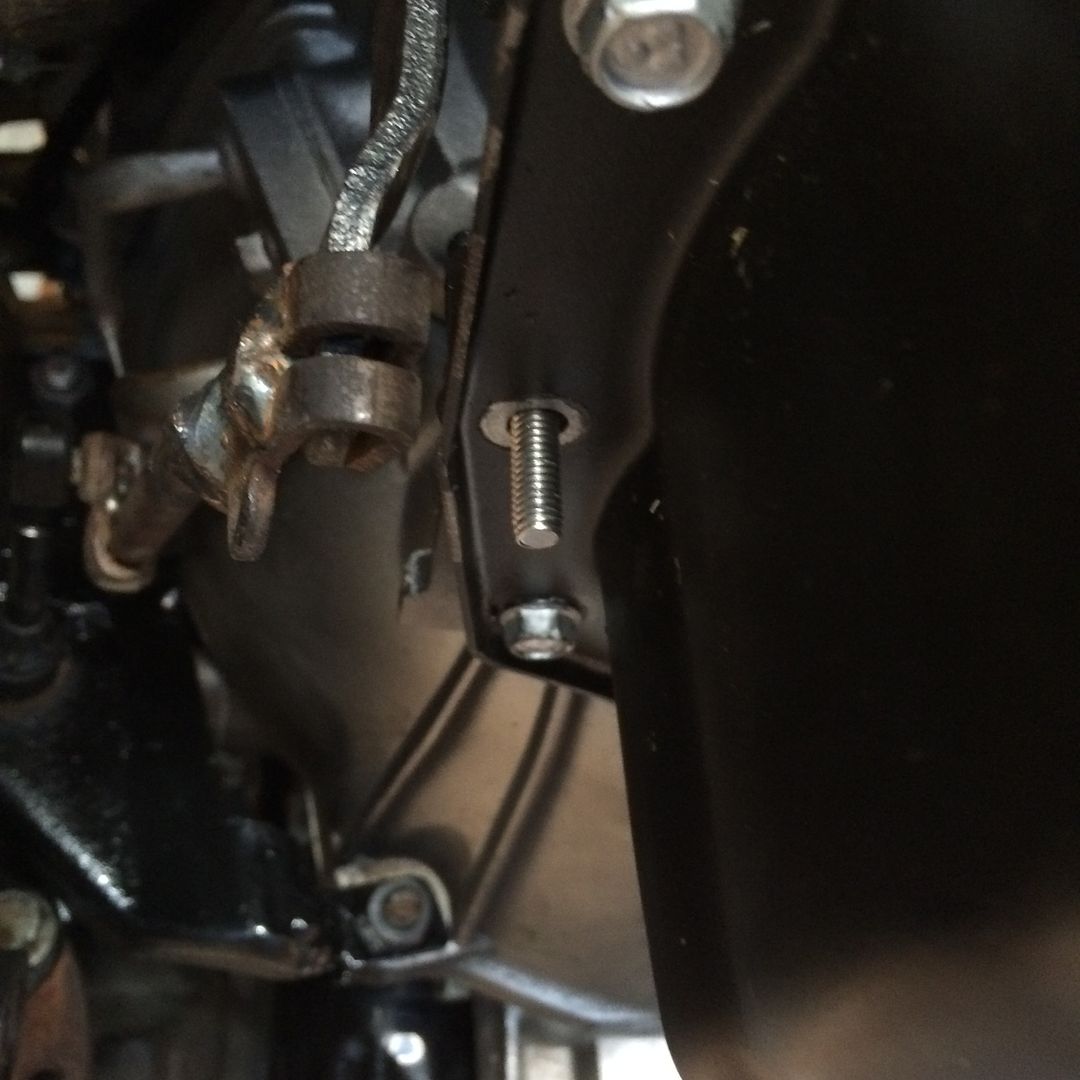 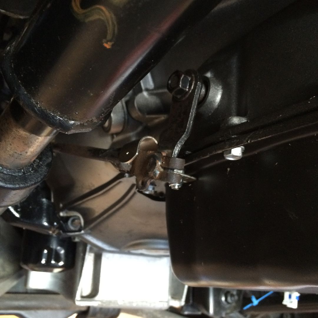 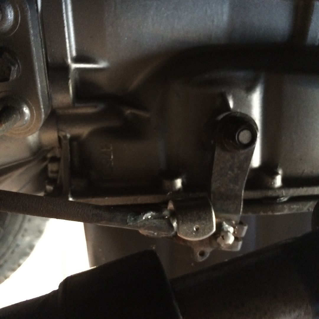 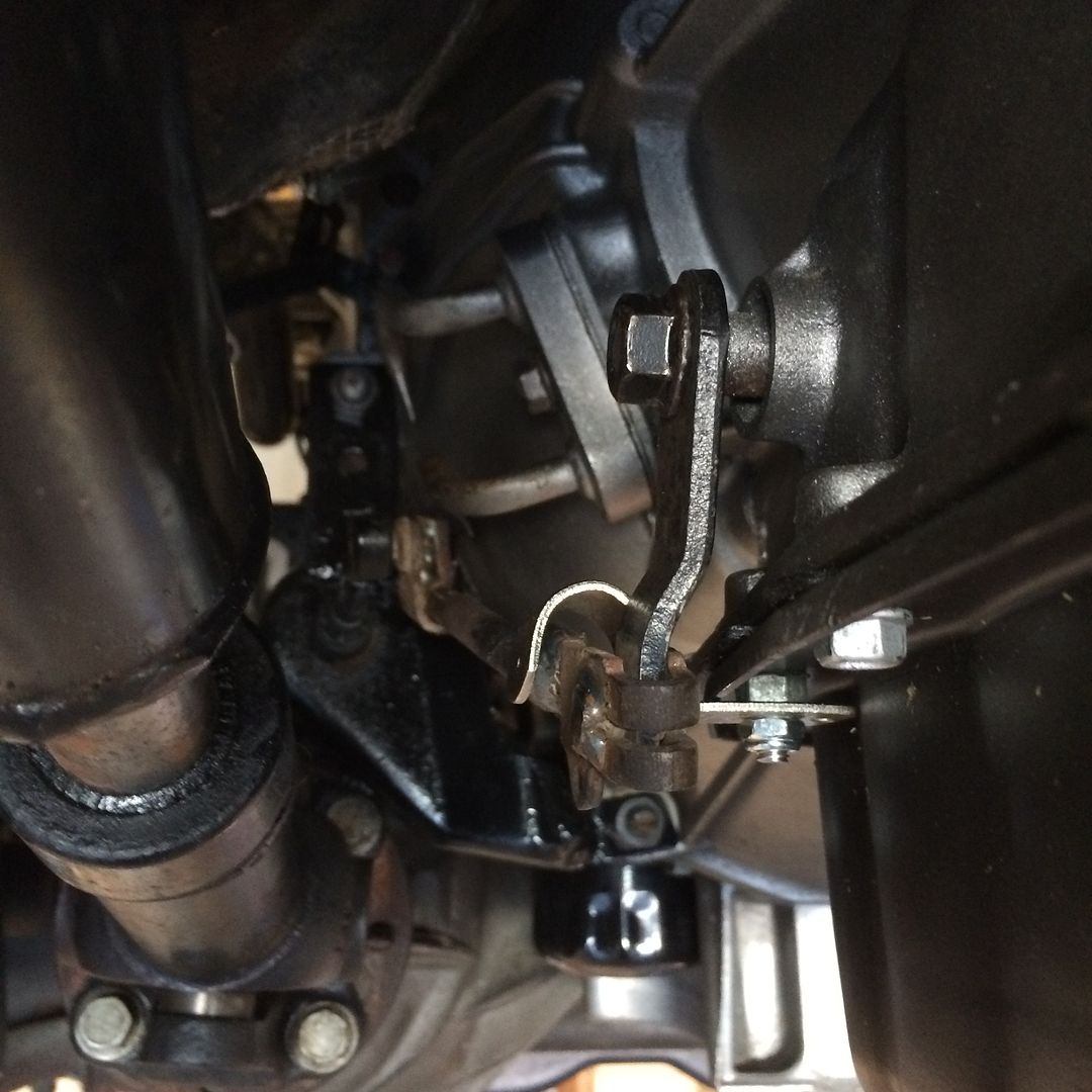 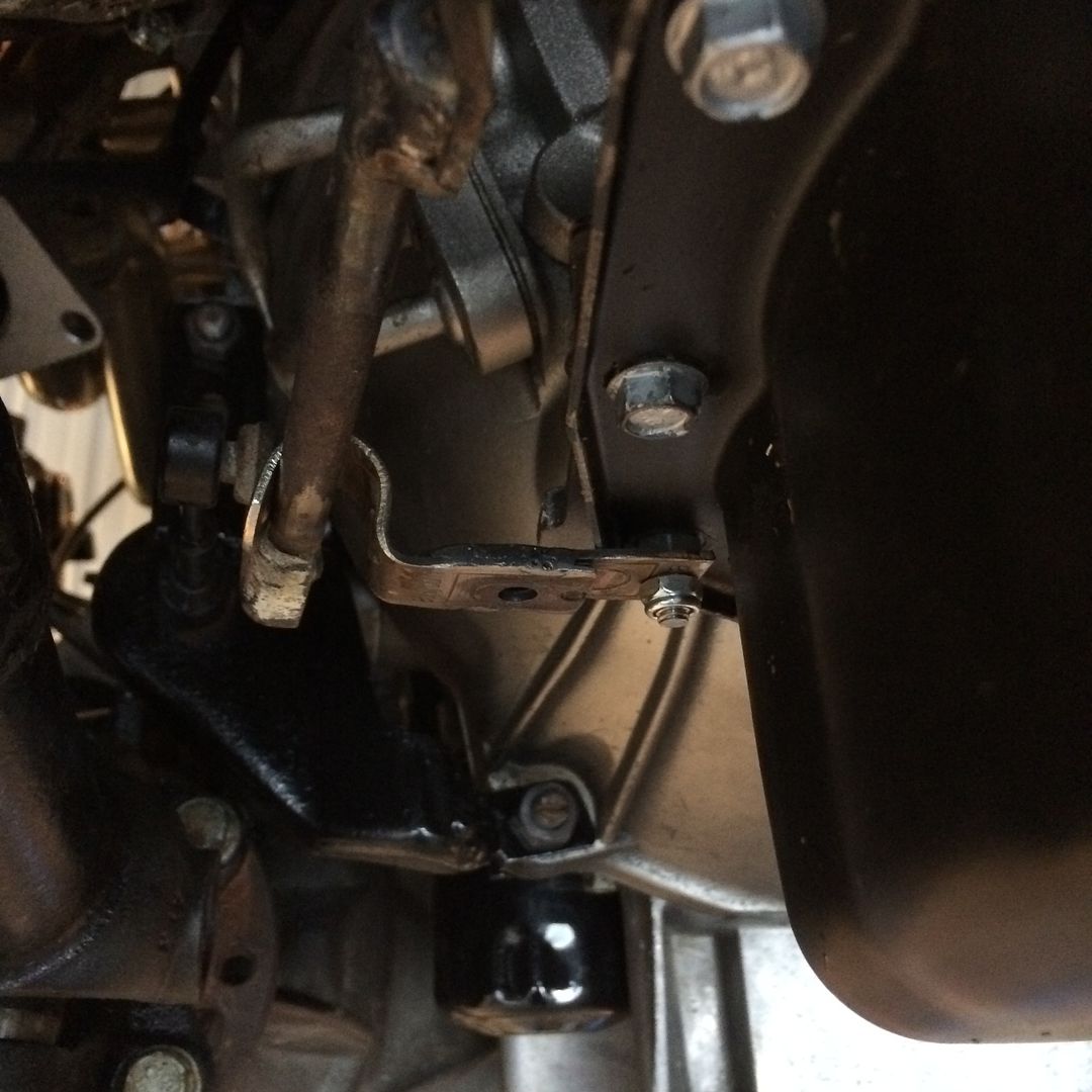 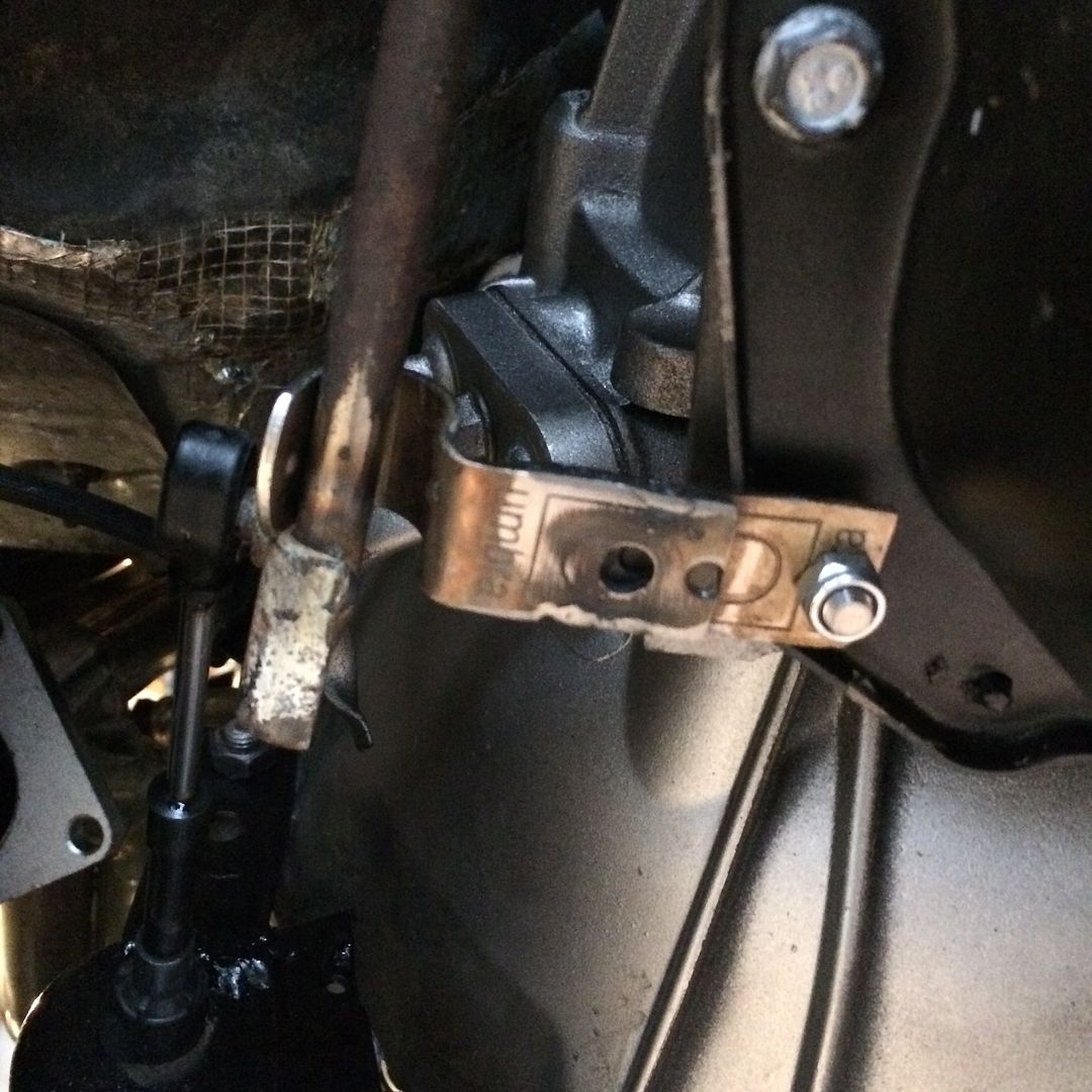 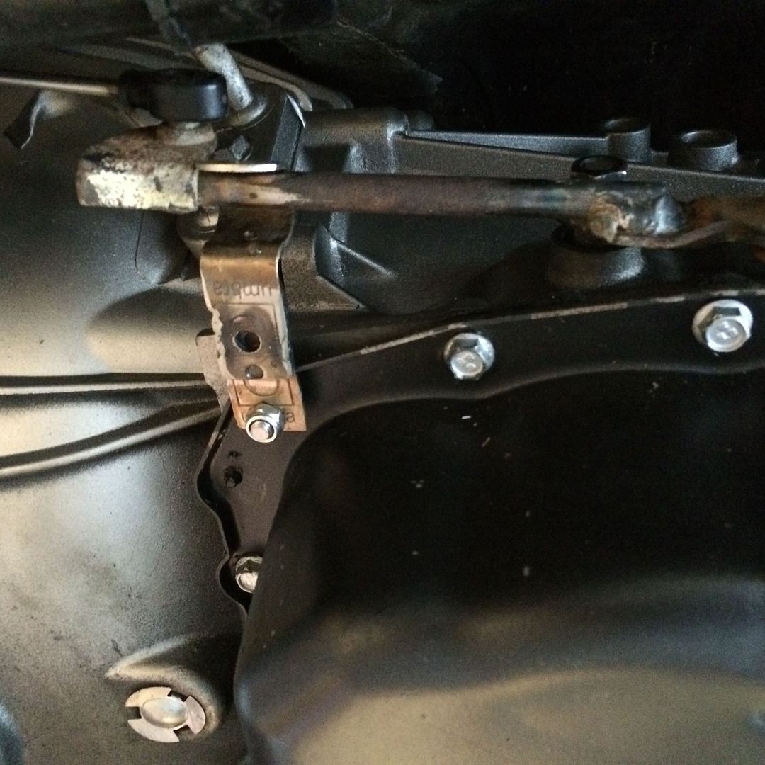 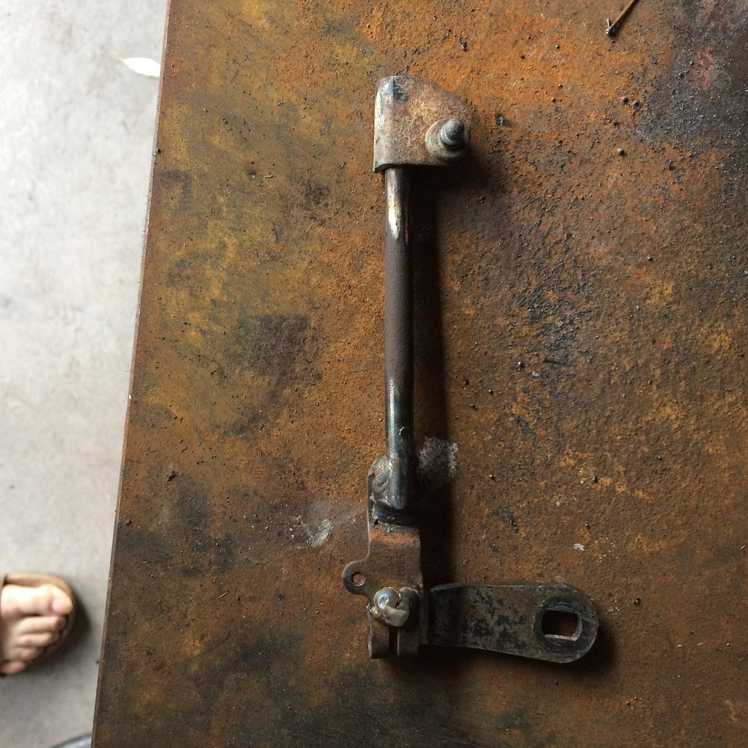 |
|
|
|
Post by casias on Jun 19, 2016 18:02:37 GMT -5
Not a lot of updates as far as the way the project appears, but all of the little things are coming right along. I added the wiring harness and mounted the ECU in the passenger fender, just behind the headlight. I left the space for the original Dodge ECU open, because I plan on using it for gauges in the beginning. So unfortunately, the ugly Dodge harness will have to lay on my new harness. I am going to trim it down as much as I can, and wrap it in new loom. Also, I found a belt for my custom accessory drive. I used a nylon tie down to estimate the length I needed and came up with 102 inches more or less. Using the gates belt chart, I bought about 6 belts in each direction from K061020 (which is 102 5/8), and found that the K061030 was perfect at 103 inches. (Dayco also has a really nice lookup tool on the internet for belt sizes). I mounted the power steering reservoir, and used the original Dodge power steering lines with a little tweaking to get around the serpentine belt. Filled the system with Dexron III, and hand-primed it. Then I mounted the LS3 gold-blade throttle body, and took some time carefully laying the harness wires and securing them on the engine with cushion clamps. I have been though having torn wires before, and I don't want it to happen again. Contrary to what I was finding on the internet, the LS3 throttle body clears the LSA pulley without being flipped. It has about 1/4 inch of clearance, which I tried to show in a picture below. But, when I go to a smaller pulley at some point (yep), I will gain more room. Gates belt chart. 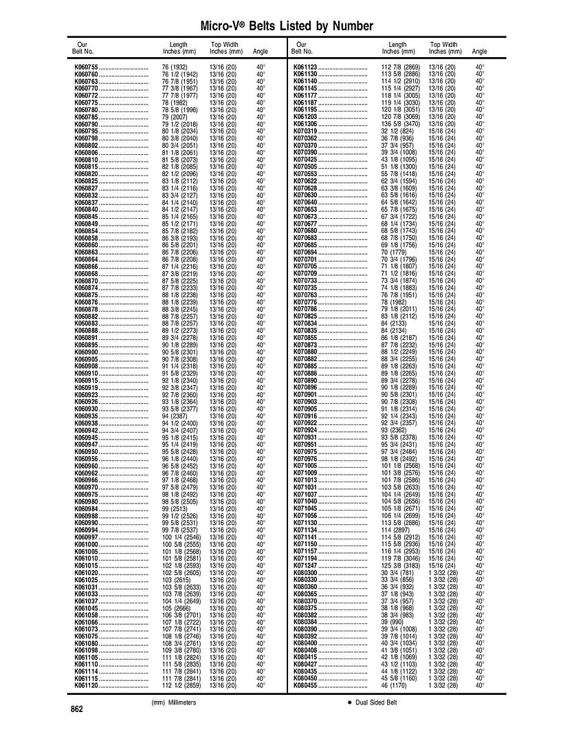 Belt 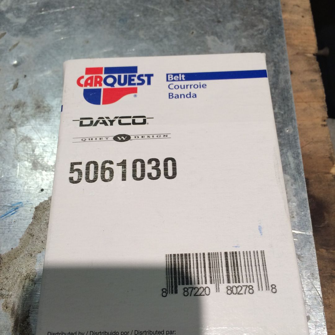 Belt. Less blue tape means things are moving right along! 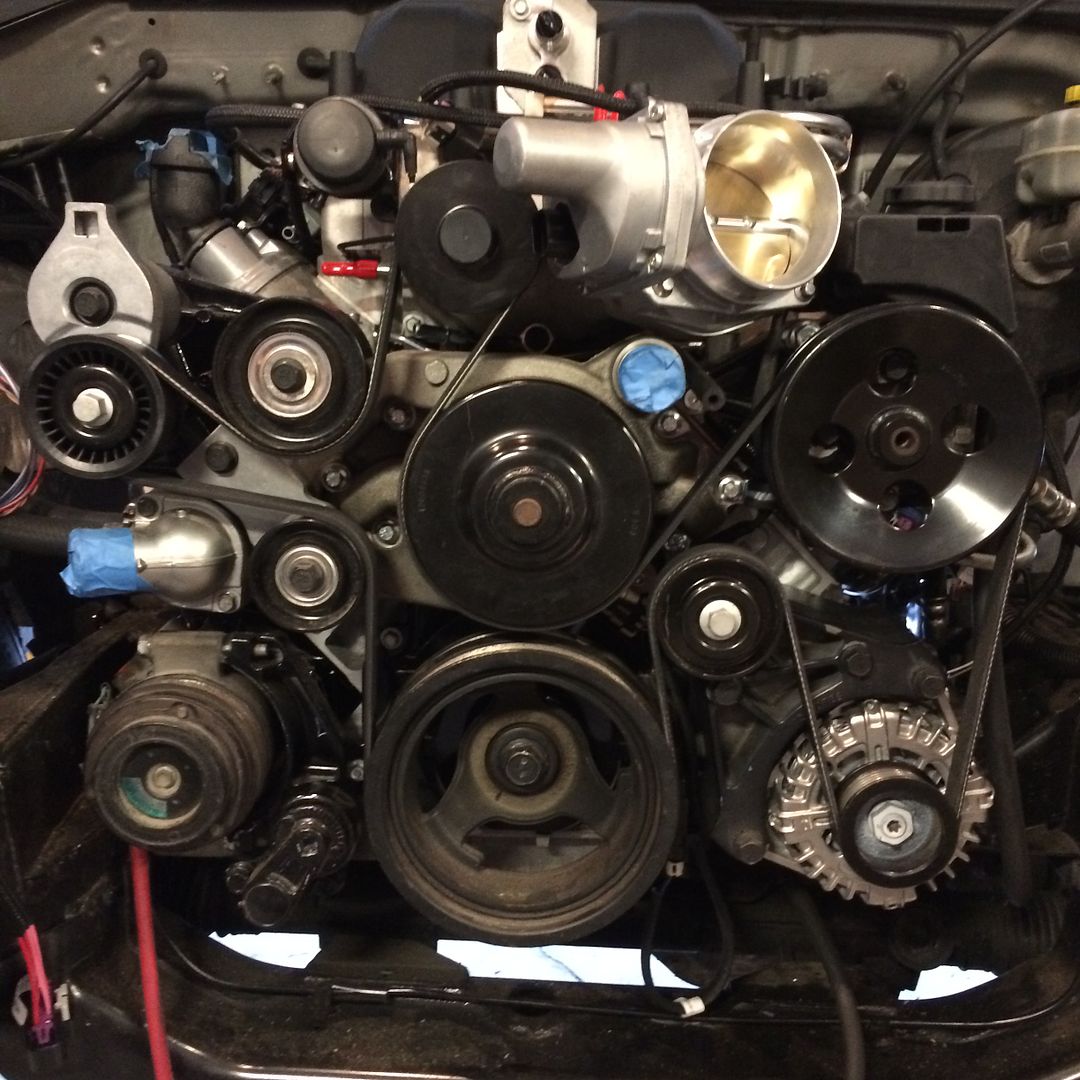 LS3 thottle body clears power steering reservoir and pulley on supercharger. 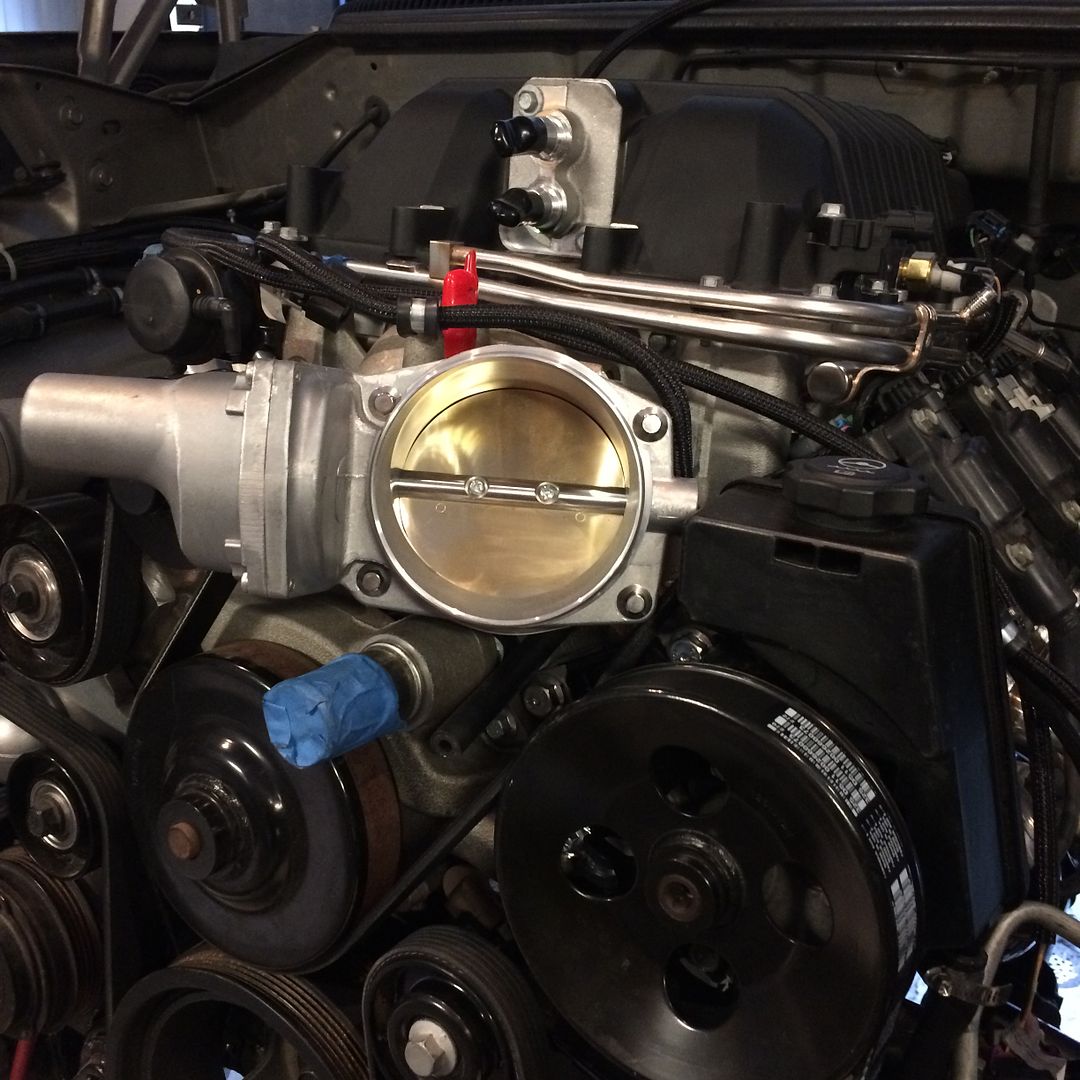 I know it looks close in this picture, but it is clear. No rubbing.I do have to pull the throttle body to change the belt, but hopefully that won't be for a long time. 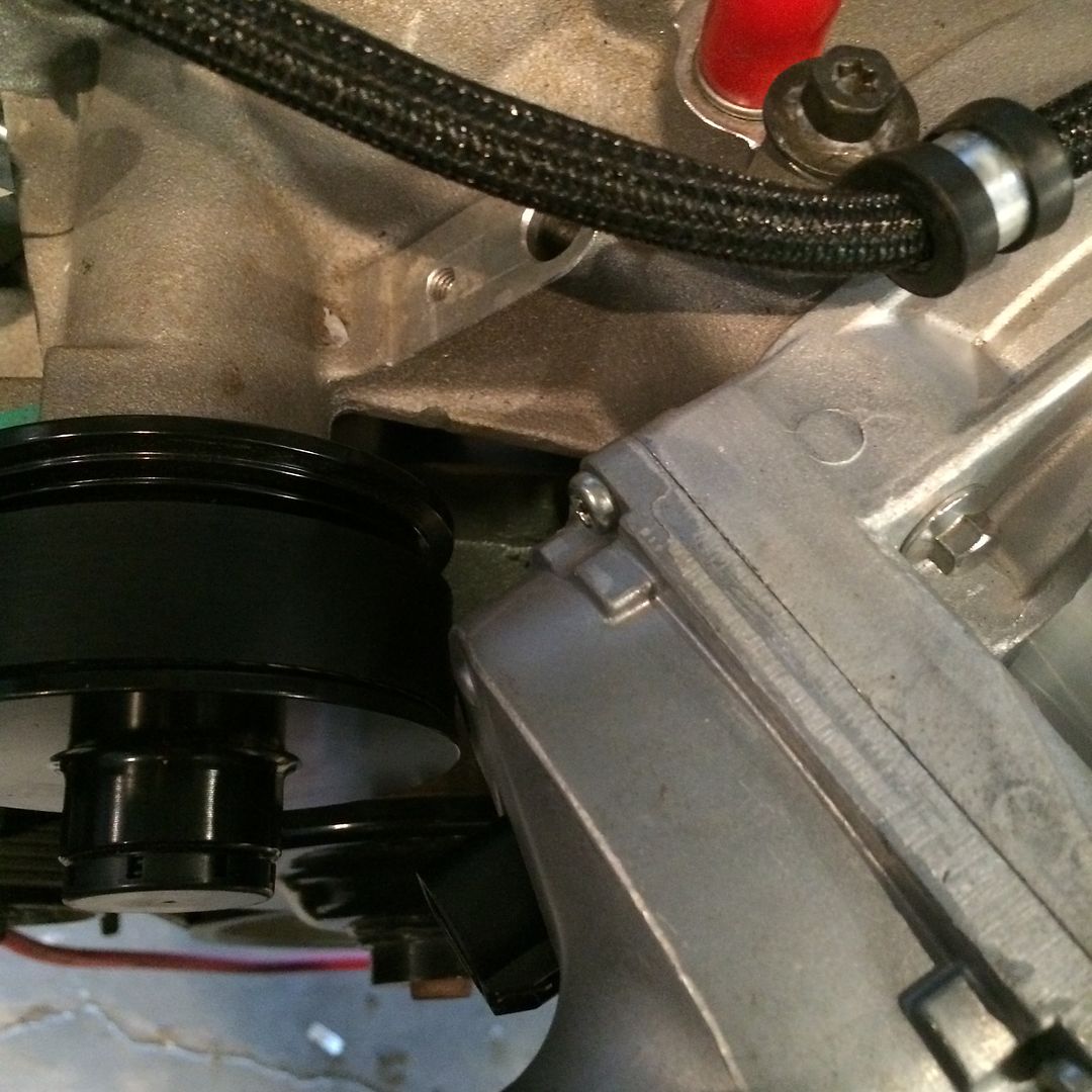 ECU mounted in passenger fender 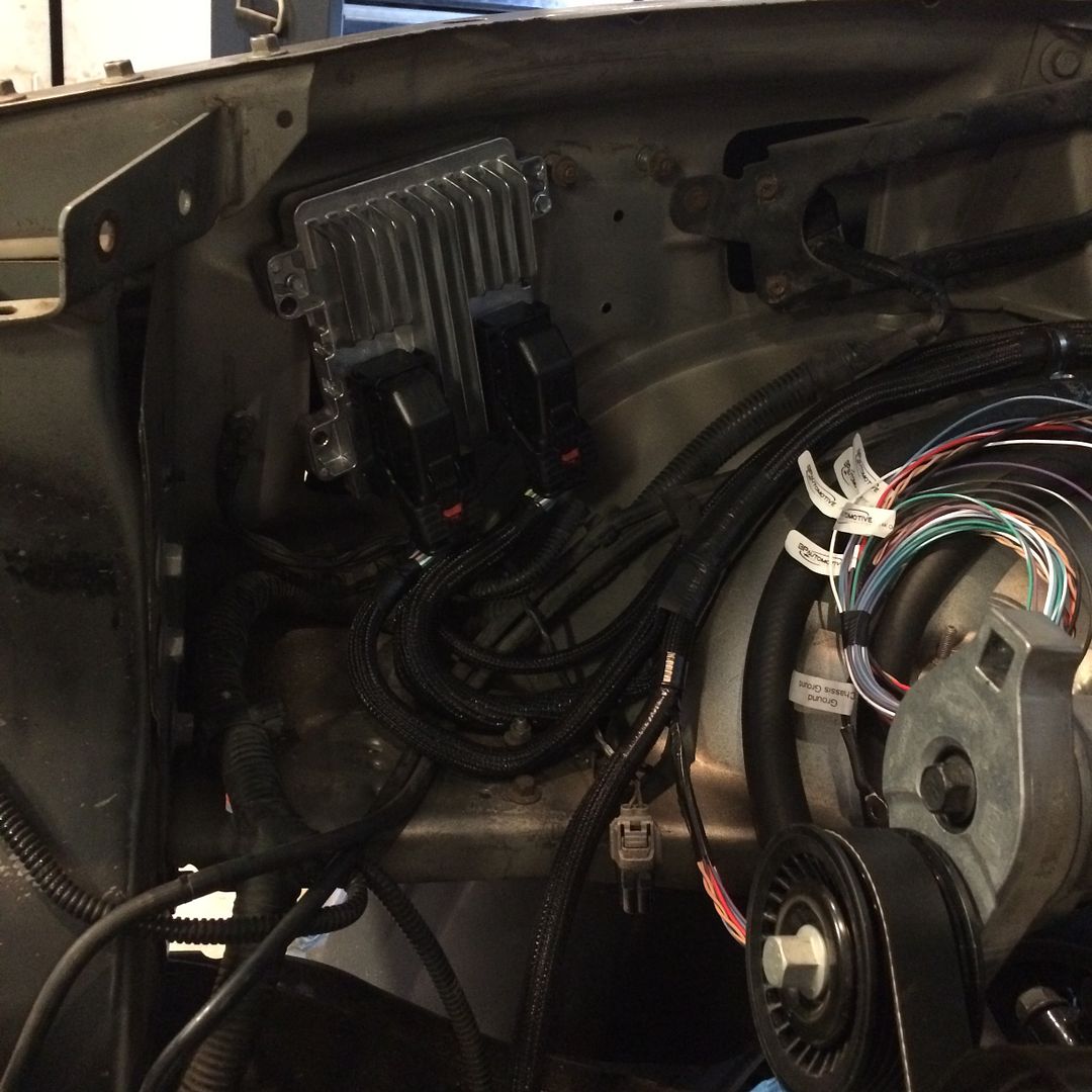 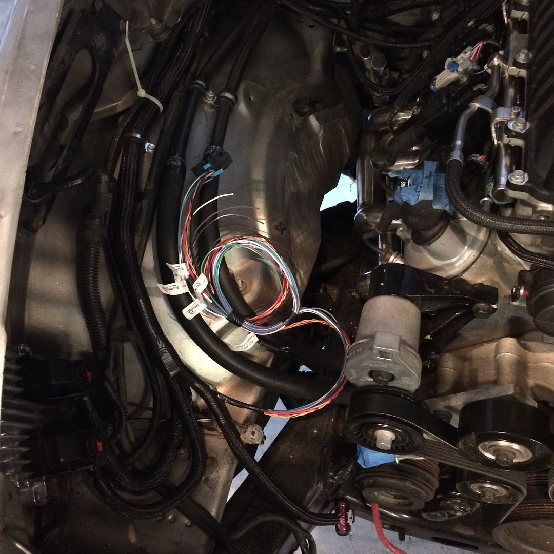 |
|
|
|
Post by casias on Jul 2, 2016 12:14:45 GMT -5
Ok. So it feels like my build has come to a crawl. Really, I am just focusing on little things. When I did the LSDAK, I was pretty sloppy with the fuel lines, electrical, intake, etc. Mostly just zip ties, duct tape, hardware store parts (ok, I still use hardware store parts), and sometimes just leaving stuff tucked into cavities and flopping around. Here are some pictures, in no particular order. ECU ended up mounted under to the bottom of the cab, directly under the passenger seat. I didn't really like where it was in the front corner behind the passenger headlight, because I would have had to extend the DBW lead, OBD lead, and a few others that have to reach into the passenger compartment. If I attached it to the firewall, the leads for it were way too long. They would have been difficult to shorten, and I didn't want them rolled up on the firewall. So this flat spot under the passenger seat worked fine. 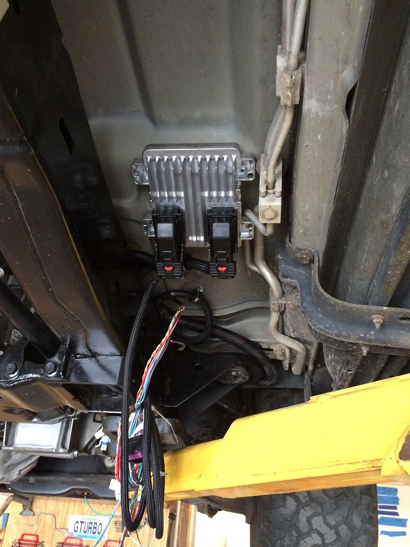 I tried to use cushion clamps everywhere. This is the starter main lead and starter trigger lead. They are the original Dodge cables, which reached exactly where they needed to go. I did have to cut the end off of the starter trigger lead, and extend it about 6 inches. Then add a ring connector to fit the LS starter. 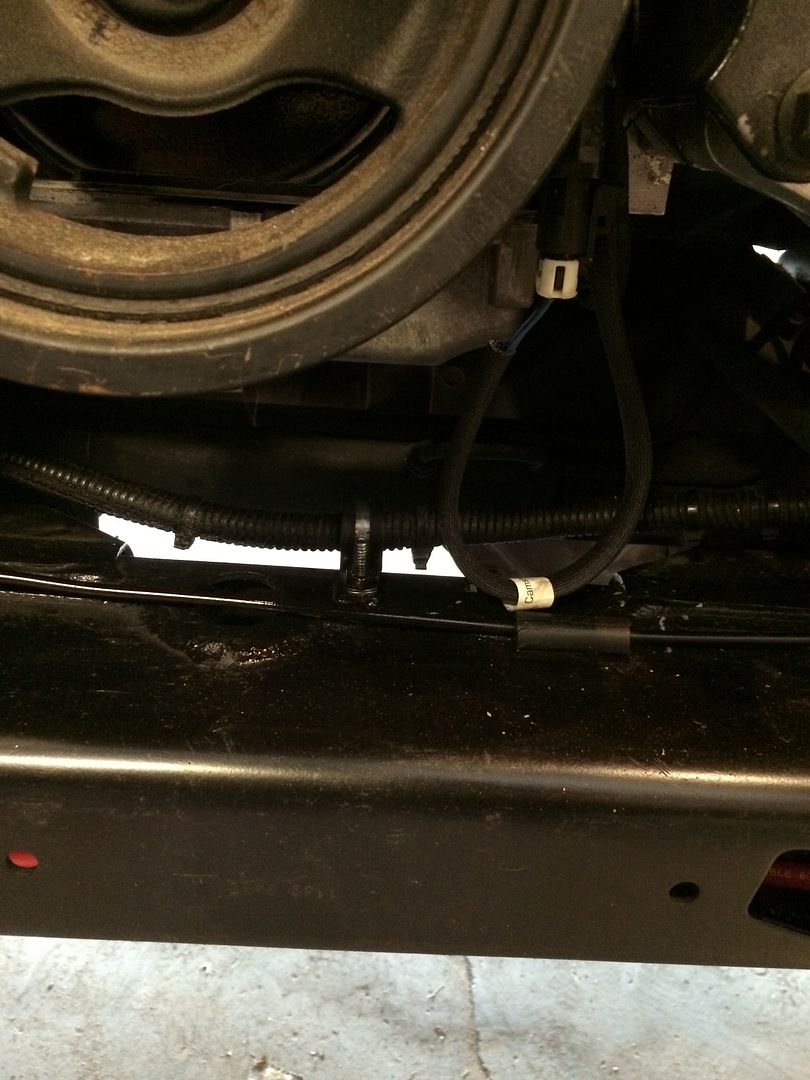 Positive battery cable from rear to front. This is inside the frame on the drivers side. Also, this is the front axle vent tube. 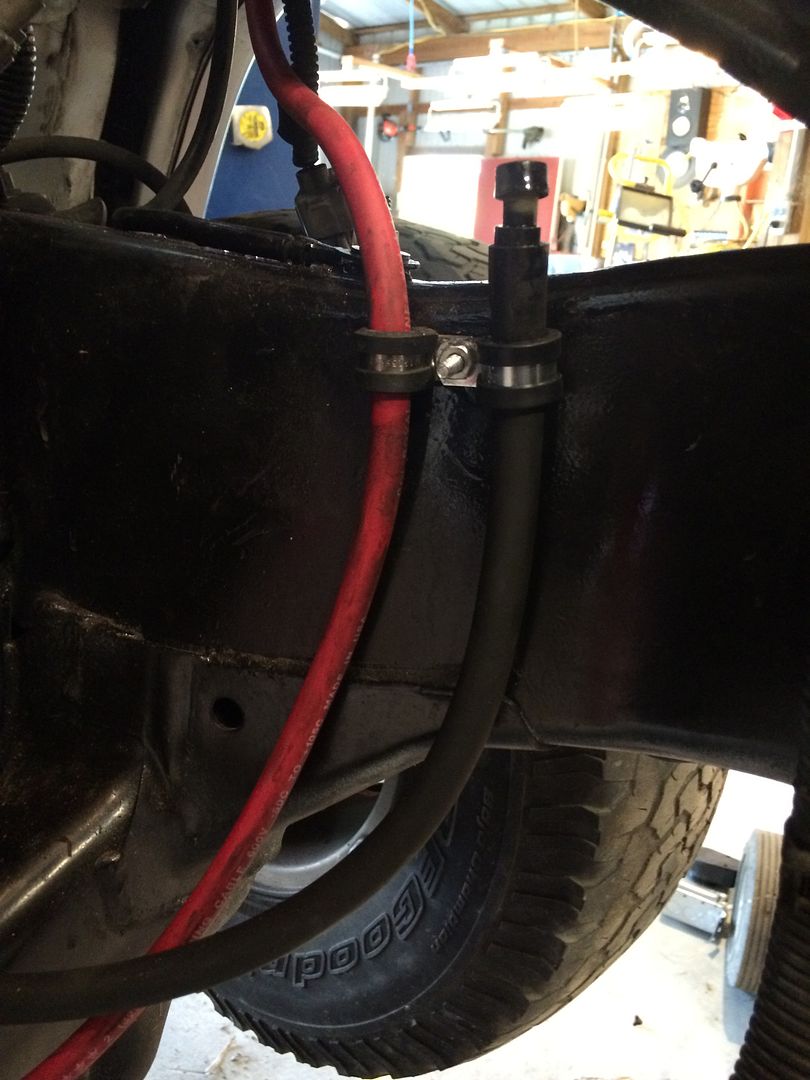 LS harness fuse box. I welded a small shelf onto the corner support in the engine bay. Also seen is the heater hoses with Gates Powergrip heat-shrink clamps, and tubing going to front and rear window washers. 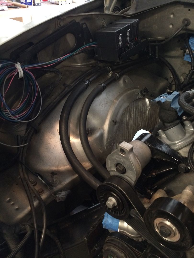 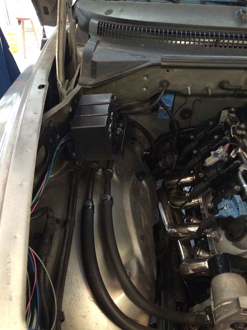 Front of the engine. I snaked the positive battery cable through the front crossmember to hide it as best I could. Also, this is the final belt arrangement. 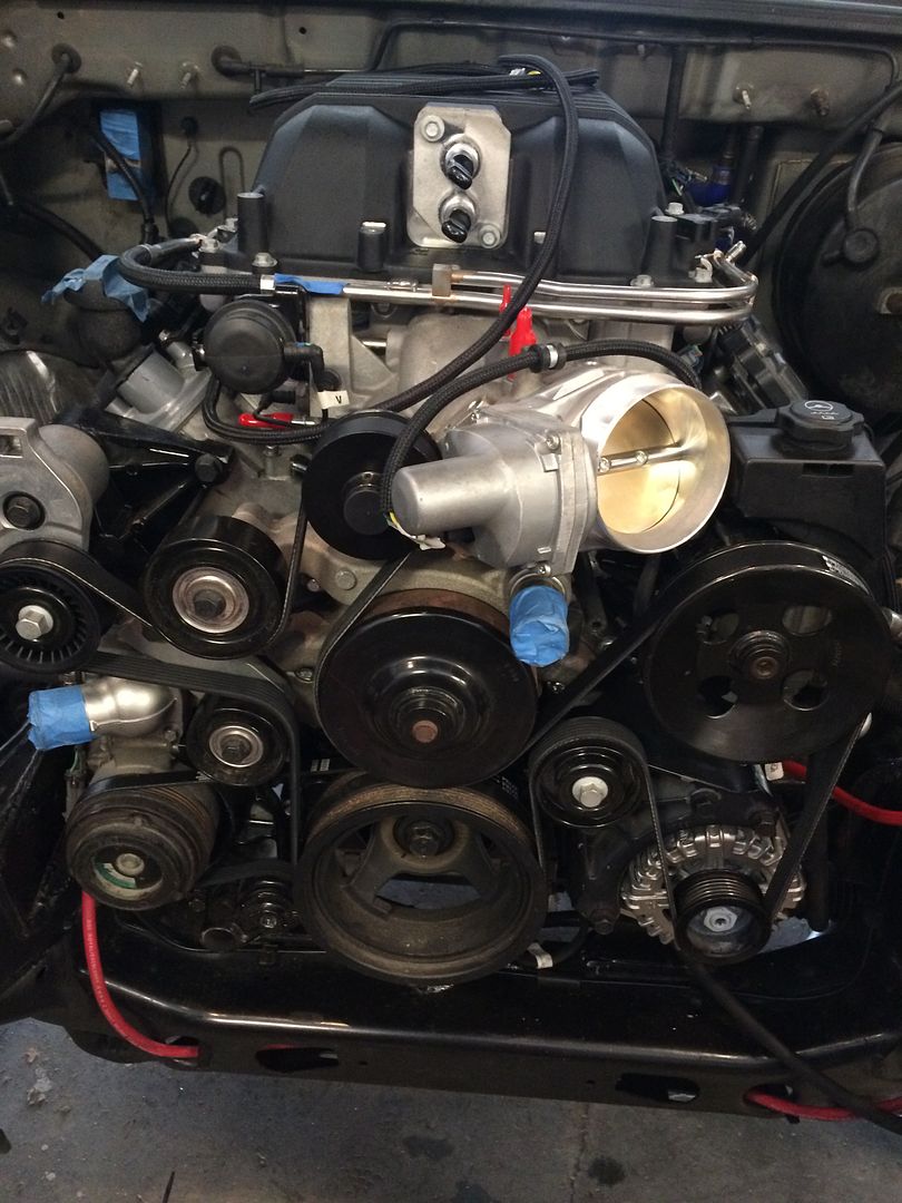 Here is the original fuse box. I pointed it down, and attached positive battery cable, alternator and starter with heavy-duty wire. This will all be hidden under the intake tubing when it is done. 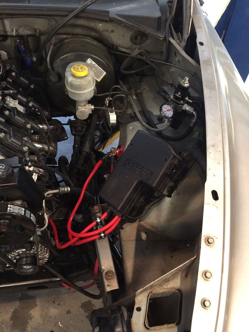 Solder-on lugs. I like to solder these on big-gauge wire, and put heatshrink over them. A throwback to my car audio days. 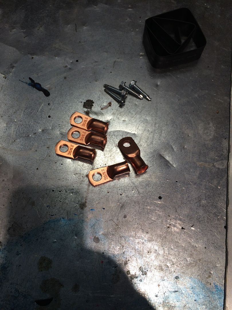 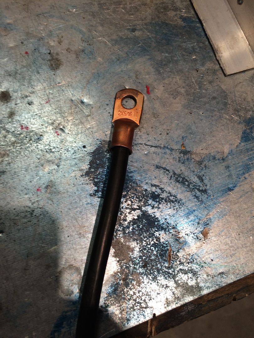 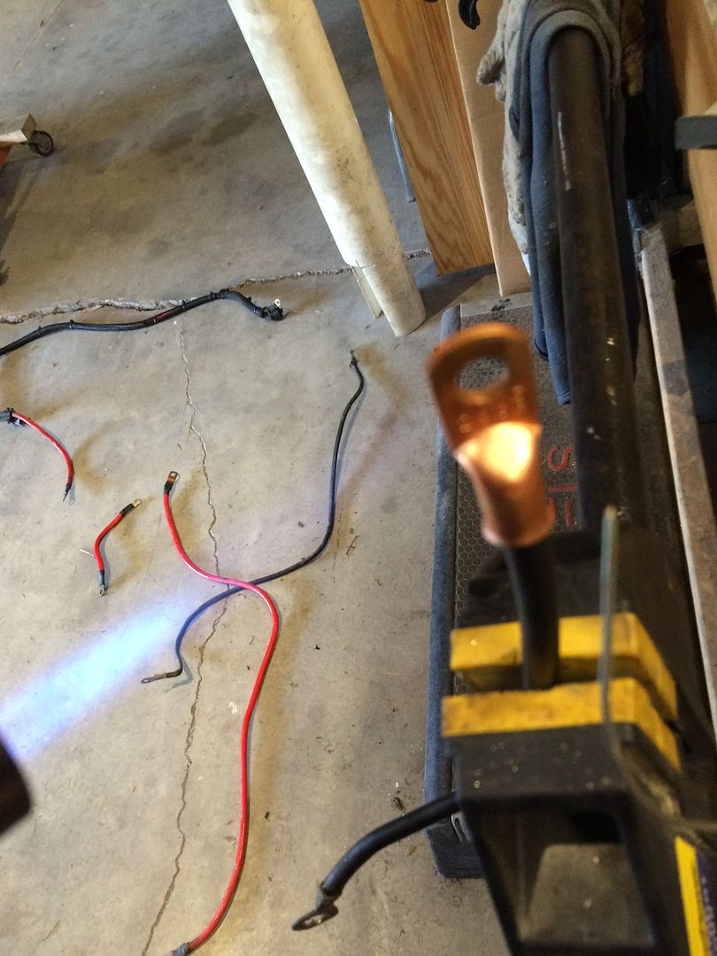 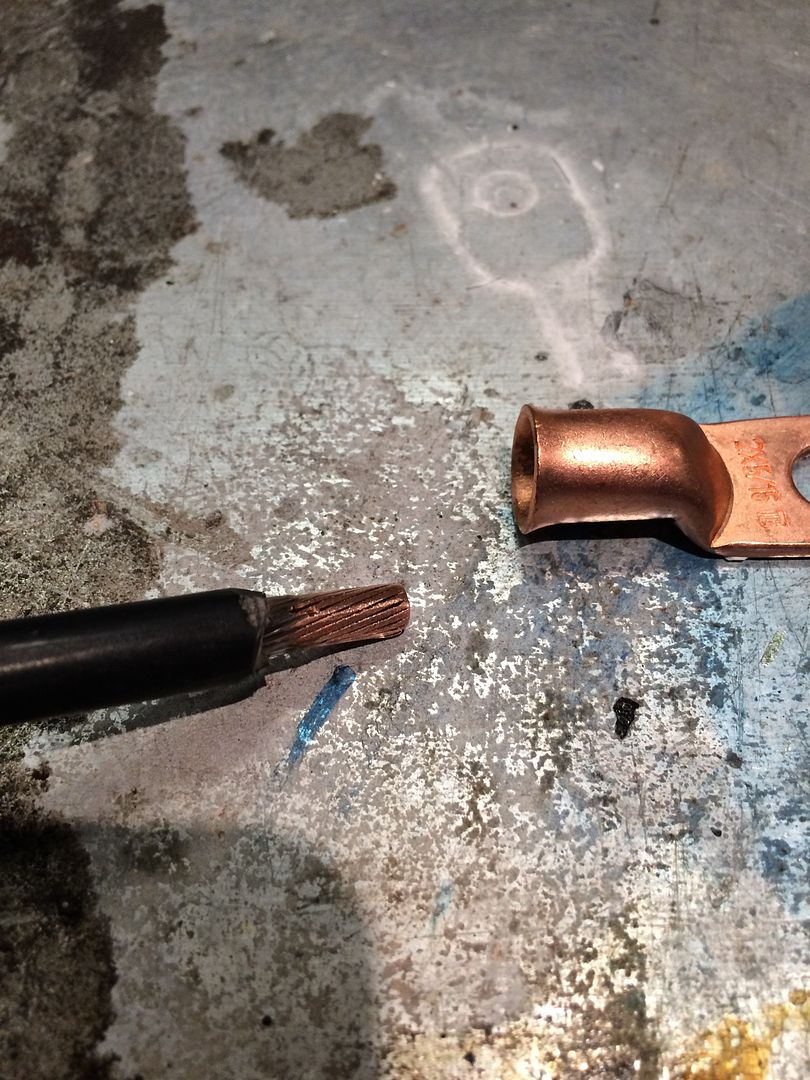 Welded bolts on the frame. I can't stand drilling holes in the frame. Not that there is anything wrong with that, it just takes too much time and hurts my arm. So I weld 1/4 inch x 3/4 inch bolts where I need them. I buy them by the pound at Tractor Supply. 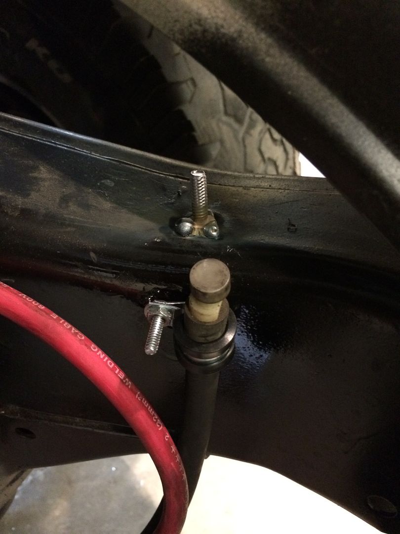 Remote battery terminals. I mounted these to the inside of the driver's side fender, so I can jump or charge the battery from inside the engine compartment. 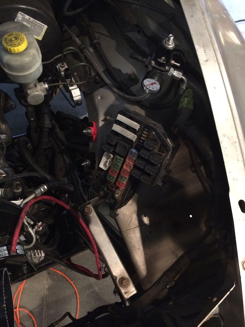 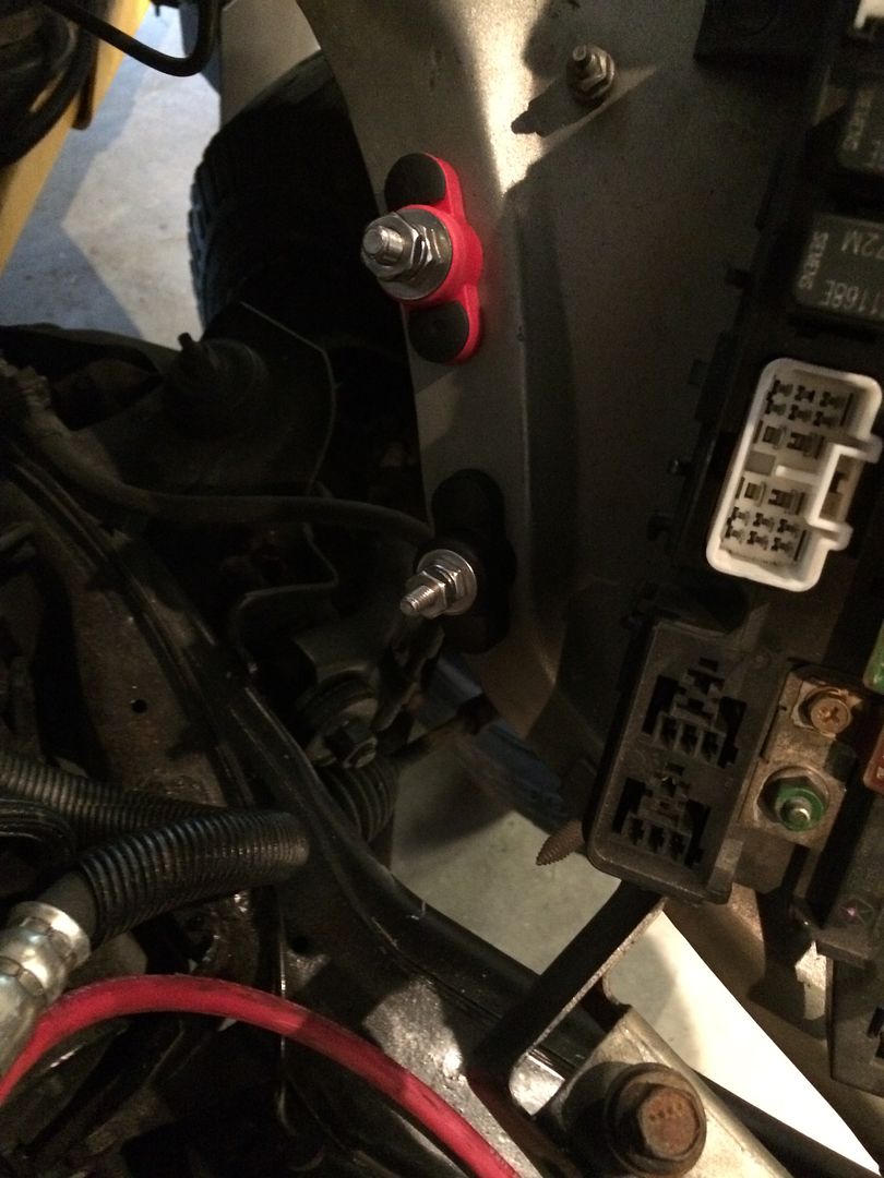 To mount them, I used push-in door panel clips. I could have used bolts, but they would rust later on. I had to clip the edge of the clips to fit, and open the holes up a little. This. 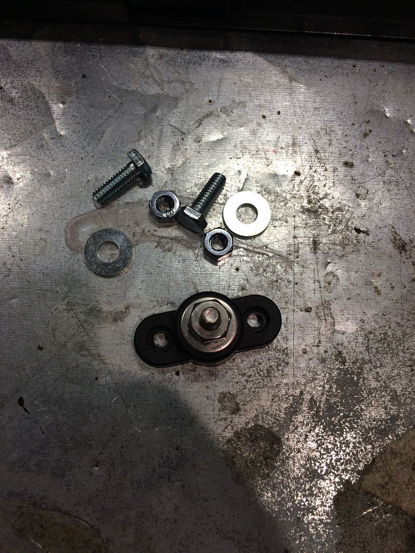 Or this. 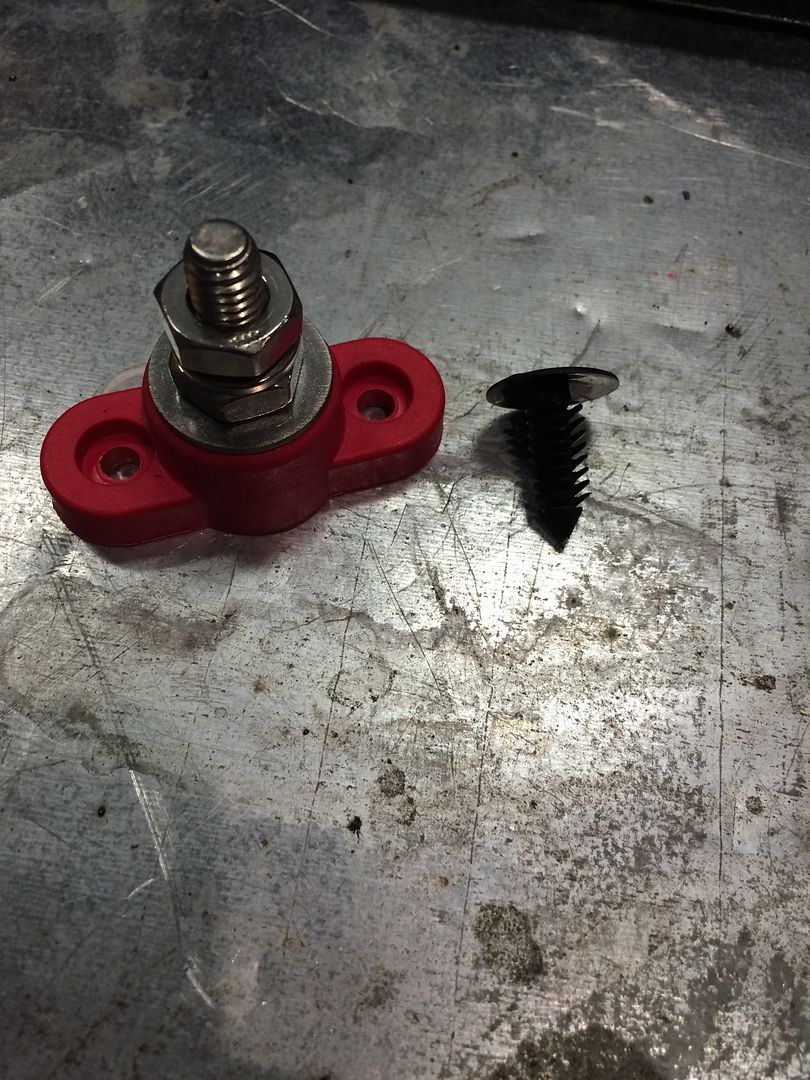 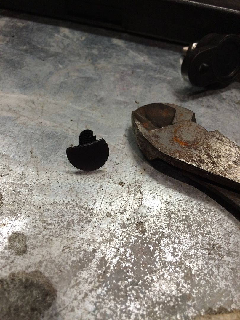 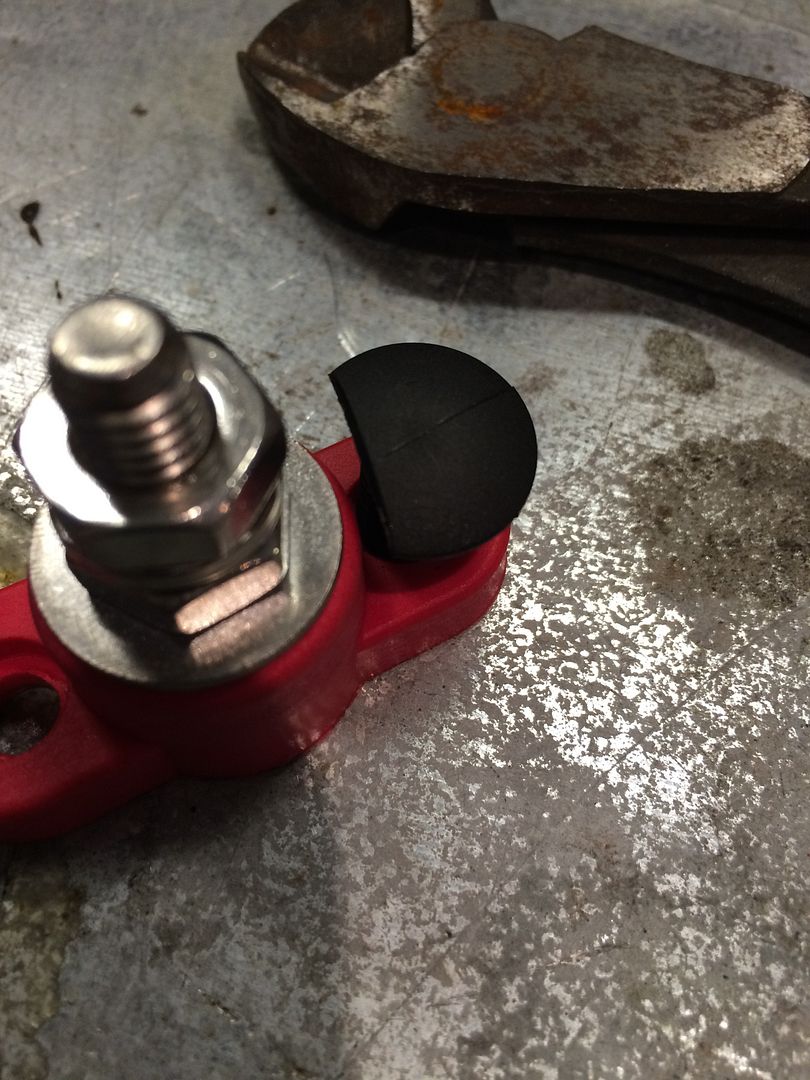 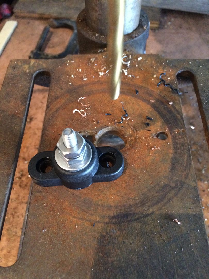 |
|
|
|
Post by sbatiste92 on Jul 2, 2016 17:14:46 GMT -5
I have to say you are really going the extra mile with this build but I think it's awesome! The neat thing about projects like this is you can see someone's mind at work through their craftsmanship. This is a really sweet build and very inspiring. Can't wait to see how it does when you drive it.
|
|
|
|
Post by casias on Jul 10, 2016 17:42:01 GMT -5
I have to say you are really going the extra mile with this build but I think it's awesome! The neat thing about projects like this is you can see someone's mind at work through their craftsmanship. This is a really sweet build and very inspiring. Can't wait to see how it does when you drive it. I'm glad you started your build. It's fun to follow along with someone else. Here was my weekend. It's about 105 in my garage, but accuweather tells us it feels like 109 outside. Not sure what it felt like in the garage, but it was hot. First project of the weekend. I am running all of this wiring, but the smaller wires don't necessarily need a cushion clamp. Also, they are bulky. I remember Dodge used these really neat clips on the original harnesses. I had a few, but needed more. My wife sat down at her 3D printer and made a pile of them. The reason I like them, besides being very neat and flat, is the wire loom (corrugated or expandable) slips over. So if you have to get to the wires, you can peel the loom back and do what you need to do, then push it back over. 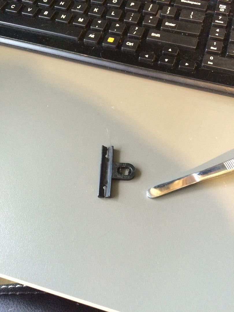 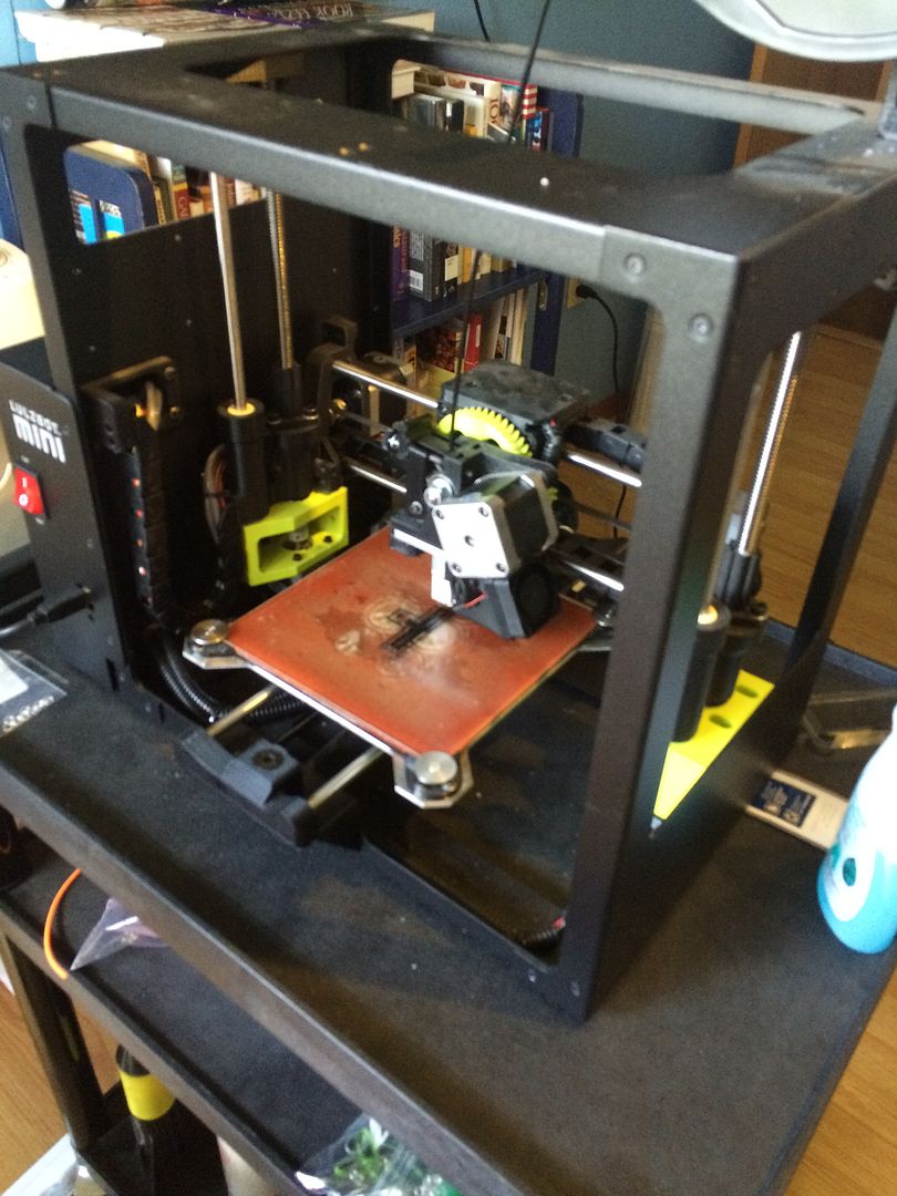 I know these look a little rough, but that's how 3D printing is. She could have increased the resolution, but it would have taken much longer. A pile of these clips took something like 15 minutes. Beats mail-order or driving somewhere (I wouldn't even know where to buy them). The other advantage is that she made them in different sizes by scaling up or down. 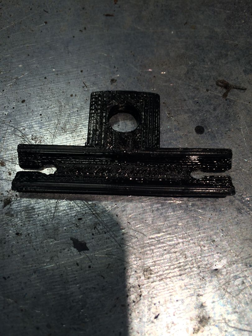 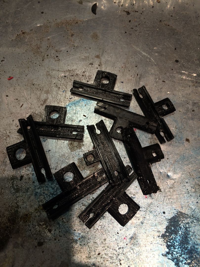 Attached to the wires with 3M electrical tape. 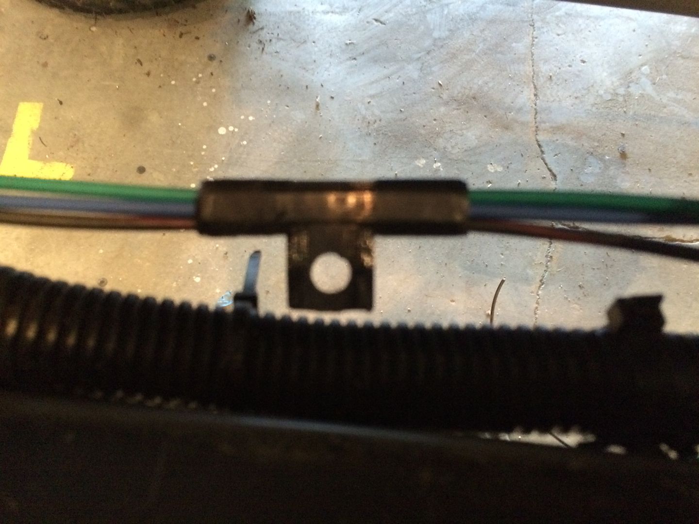 Loom slipped over. Now I just need to weld a 1/4 inch bolt on. 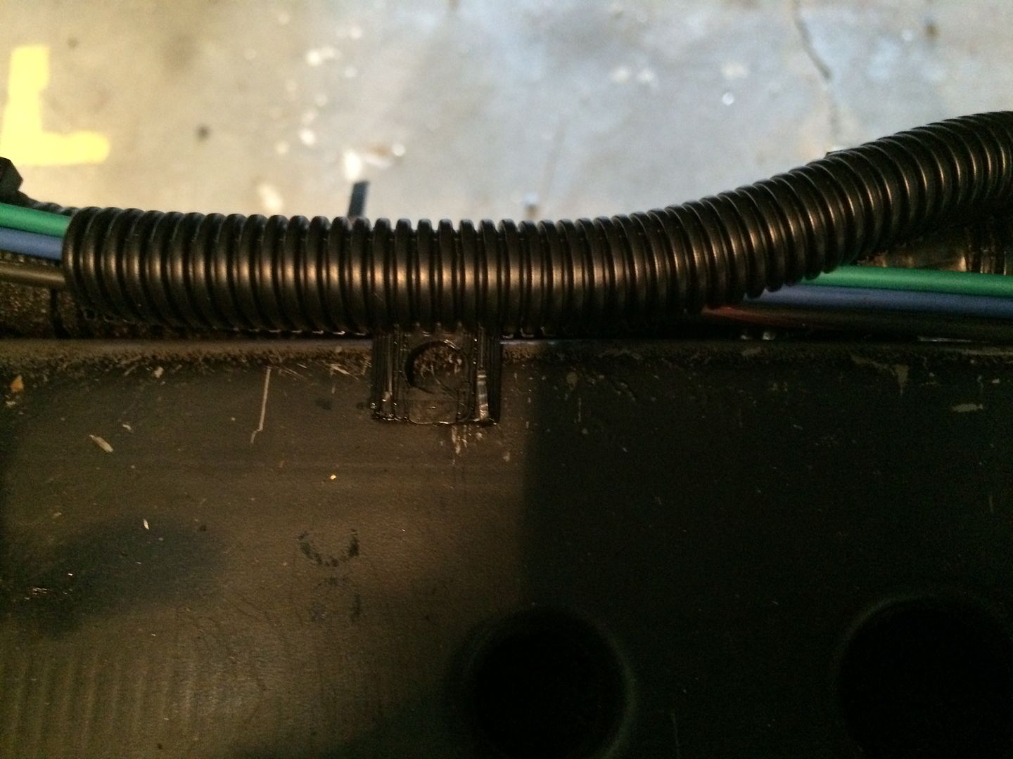 Next I primed the power steering with a 3/8 hex bit and drill. I like to test all of the systems before first start up. My son turned the wheel lock-to-lock. (Ignore the belt, I had removed it, but forgot to get a picture. So this is after I was done). 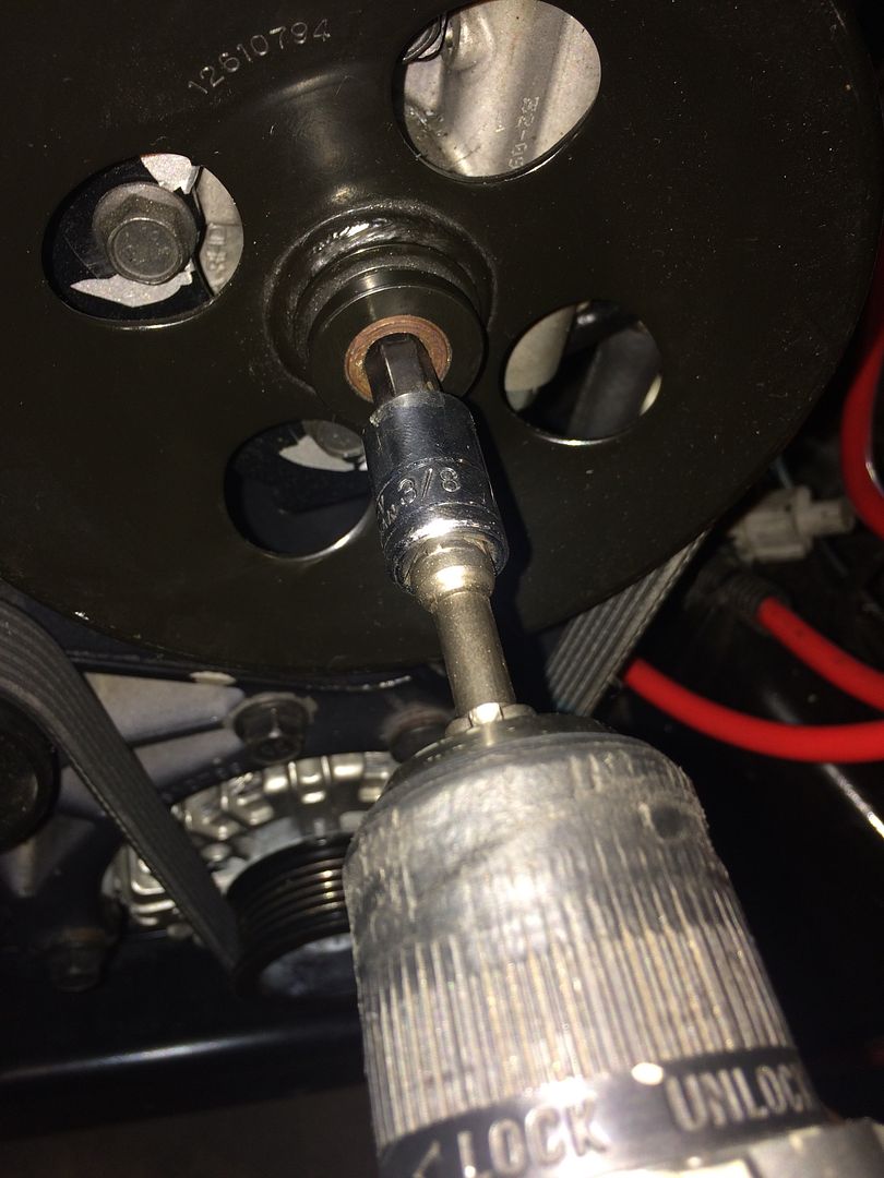 Next I hooked up the vacuum pump to bleed the brakes and test for leaks, while my son pumped the pedal. 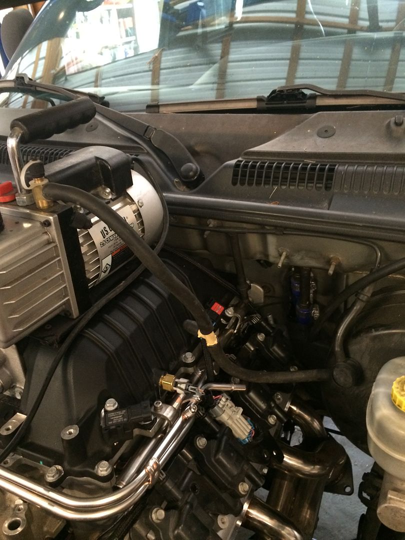 And I tried to pull a vacuum on the cooling system using a silicone coupler and test plug with a nippled drilled through it. Couldn't get a vacuum, but I ran out of time. Have to revisit this one. 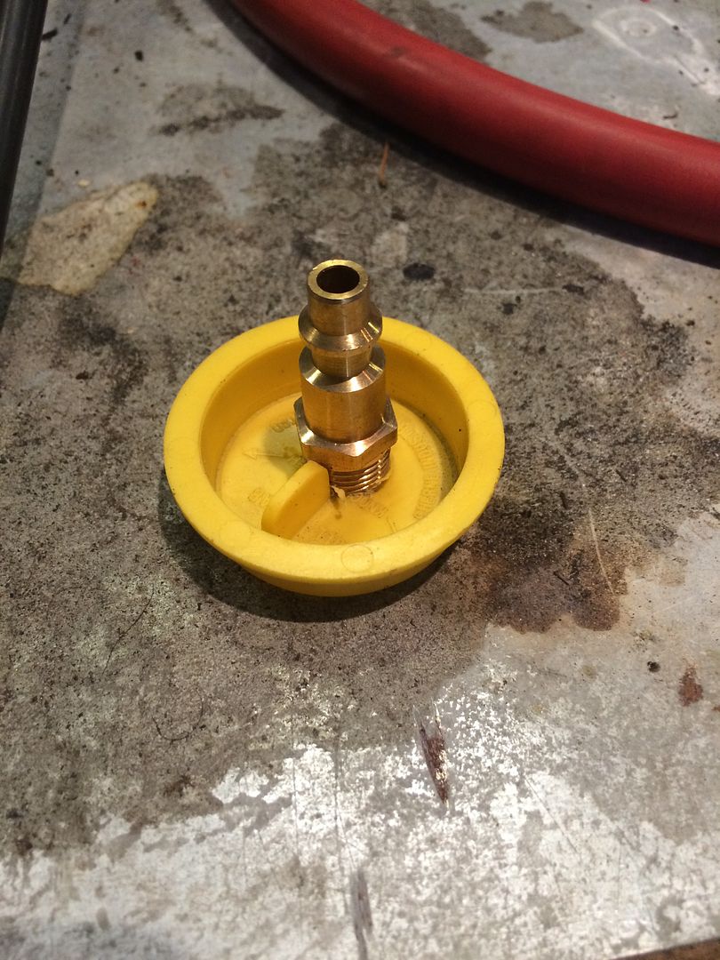 \ 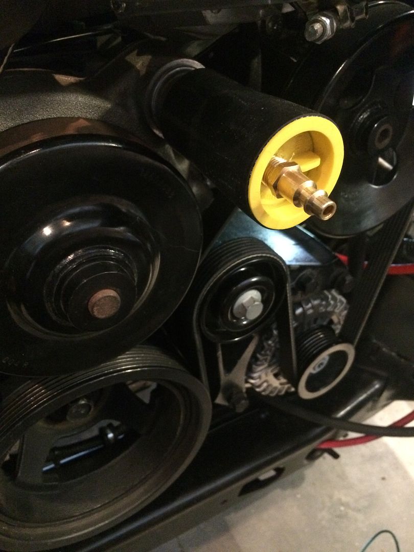 \ And finally, tested the fuel system and set the pressure. With the pump energized, The AN6 feed and AN4 return allowed me to dial down to 40 psi. That gives me plenty of headroom. So I set it for 60 psi. 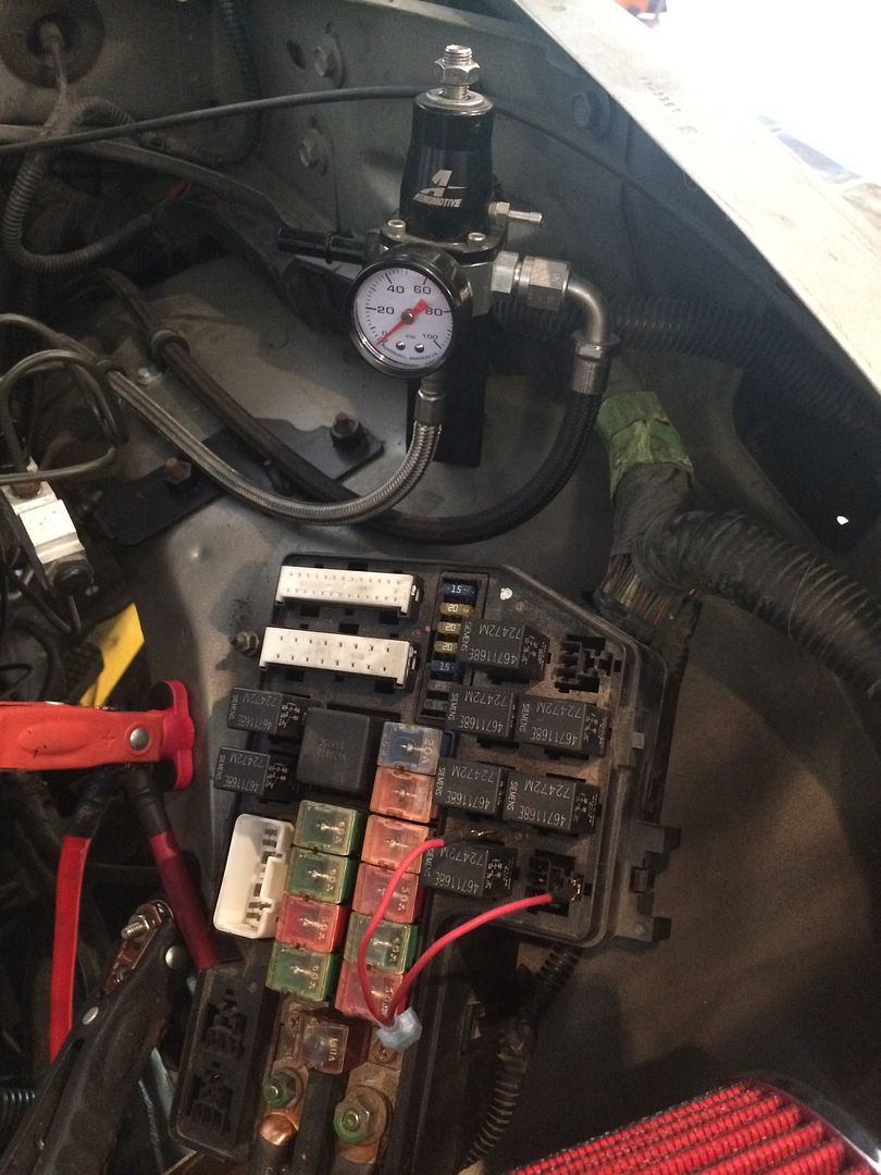 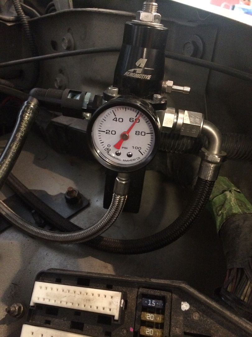 I also started mocking up the transmission cooler lines. I used the original tubing on the radiator, and attached new hose so I could make the corner onto the frame. I use a PEX crimper to hold the hose on. I have done this for years. Never had a problem. 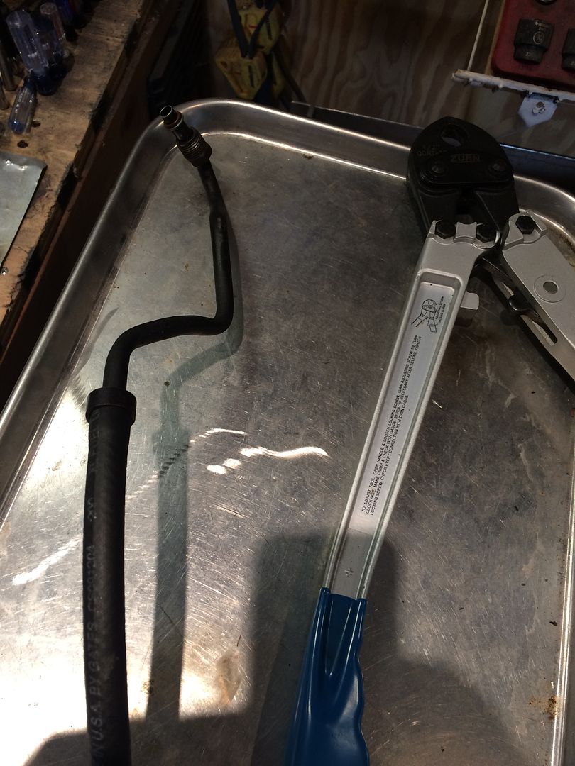 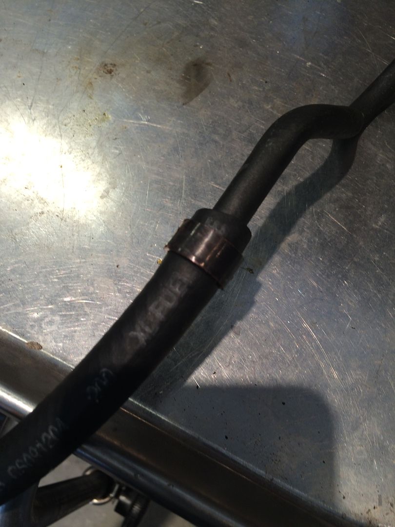 Want proof? I did these when I bypassed a leaking transmission cooler about 5 years ago. 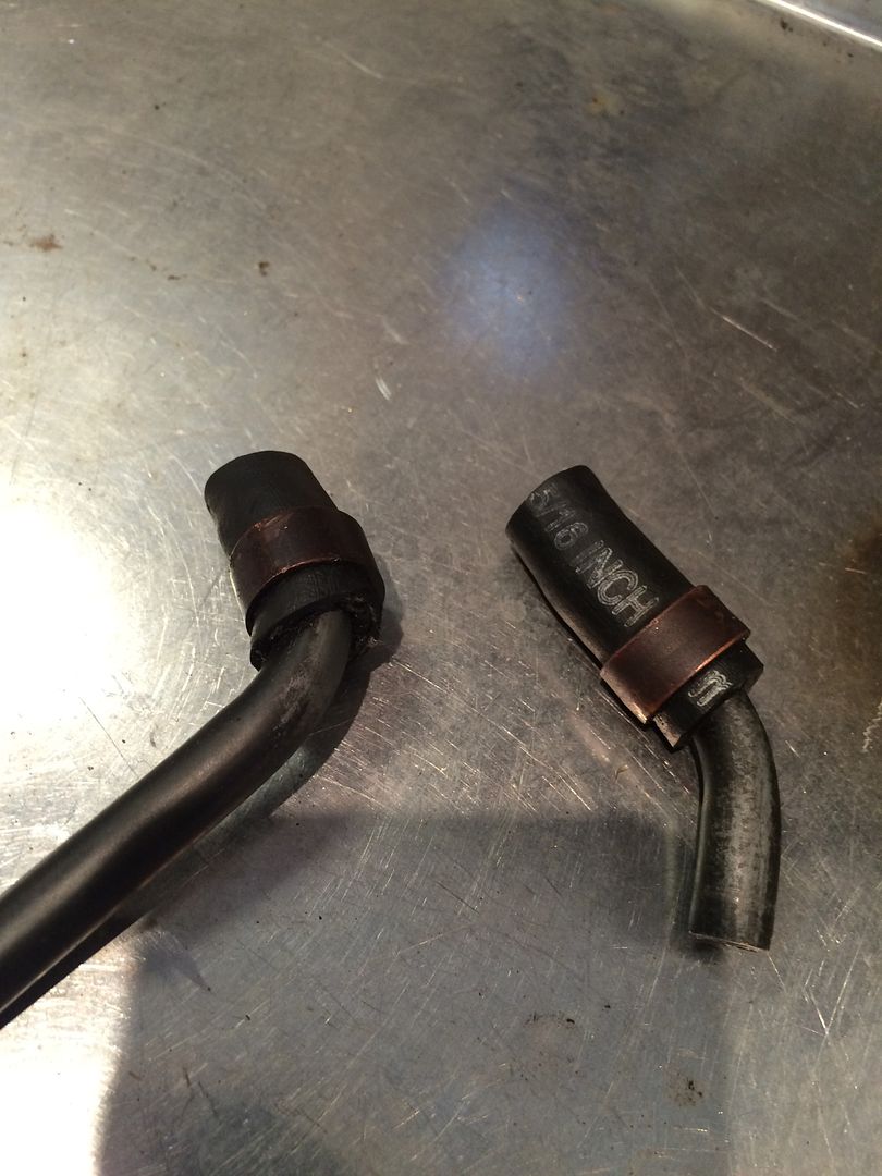 And some final pictures for the weekend. Intake is in place, beginning of the upper radiator hose is seen here. You can see the breather hose attached to the intake in my usual fashion. Brass elbow drilled through. I had to order a couple more elbows to finish the upper radiator hose. They are in the mail. 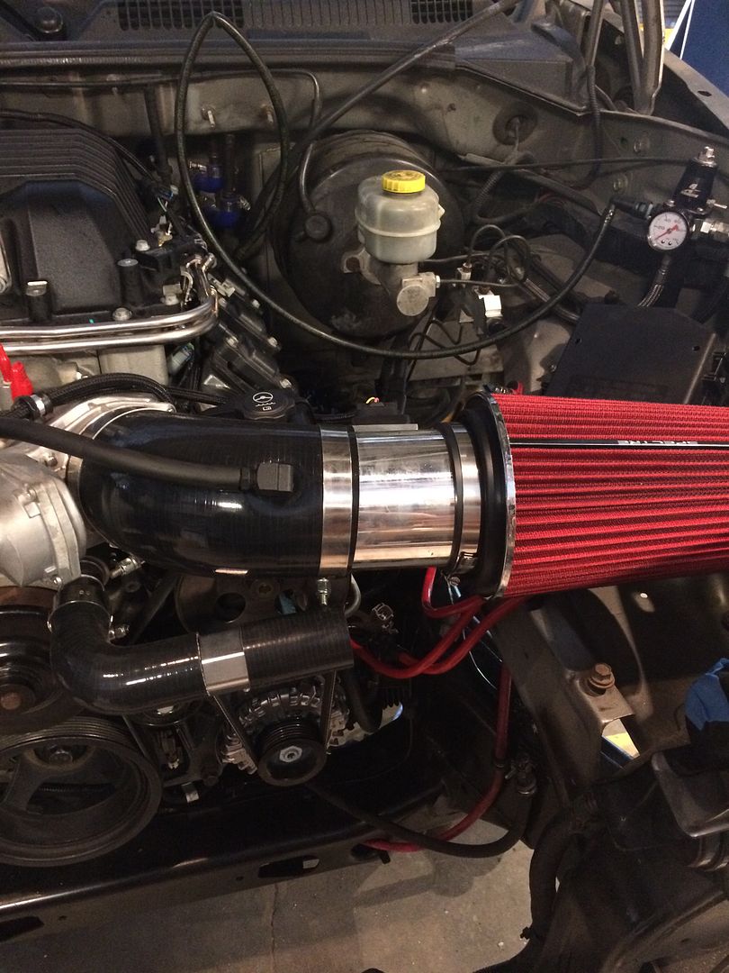 And here is a little bracket I made to keep the breather hose off of the supercharger pulley. 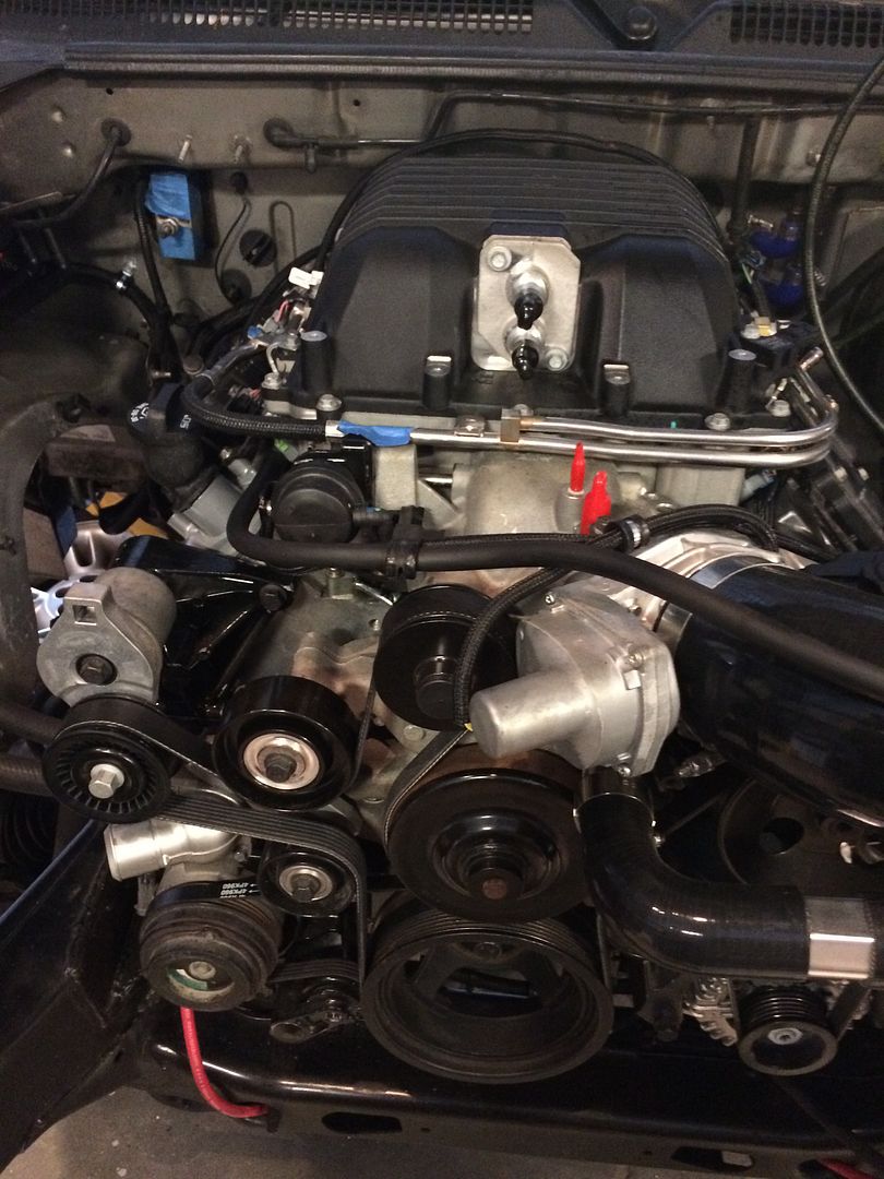 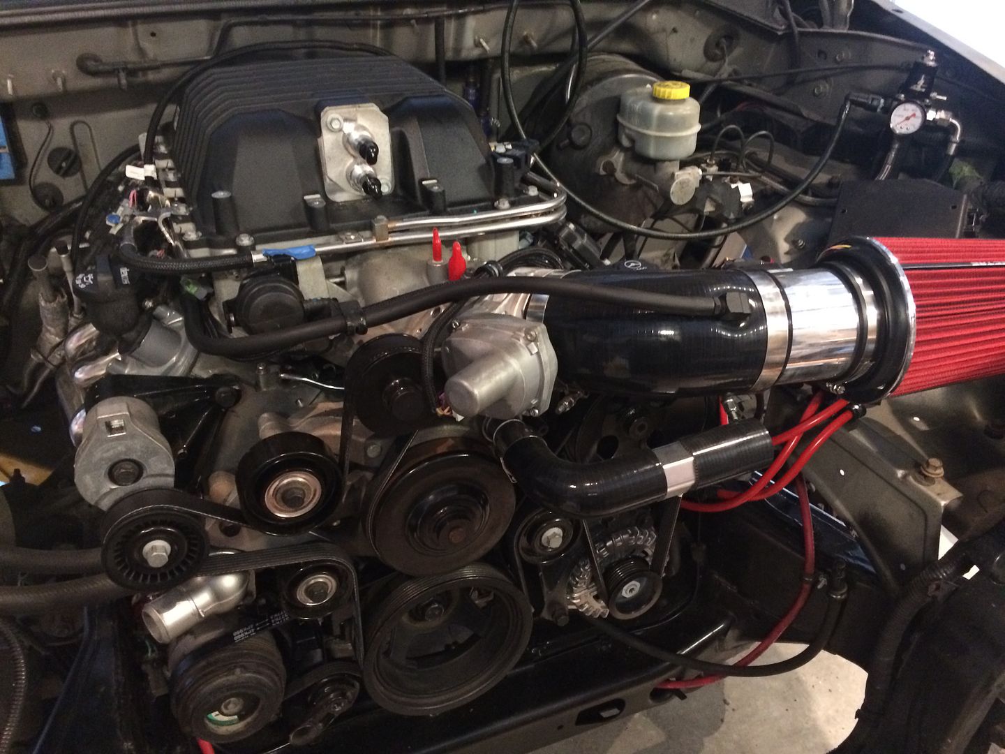 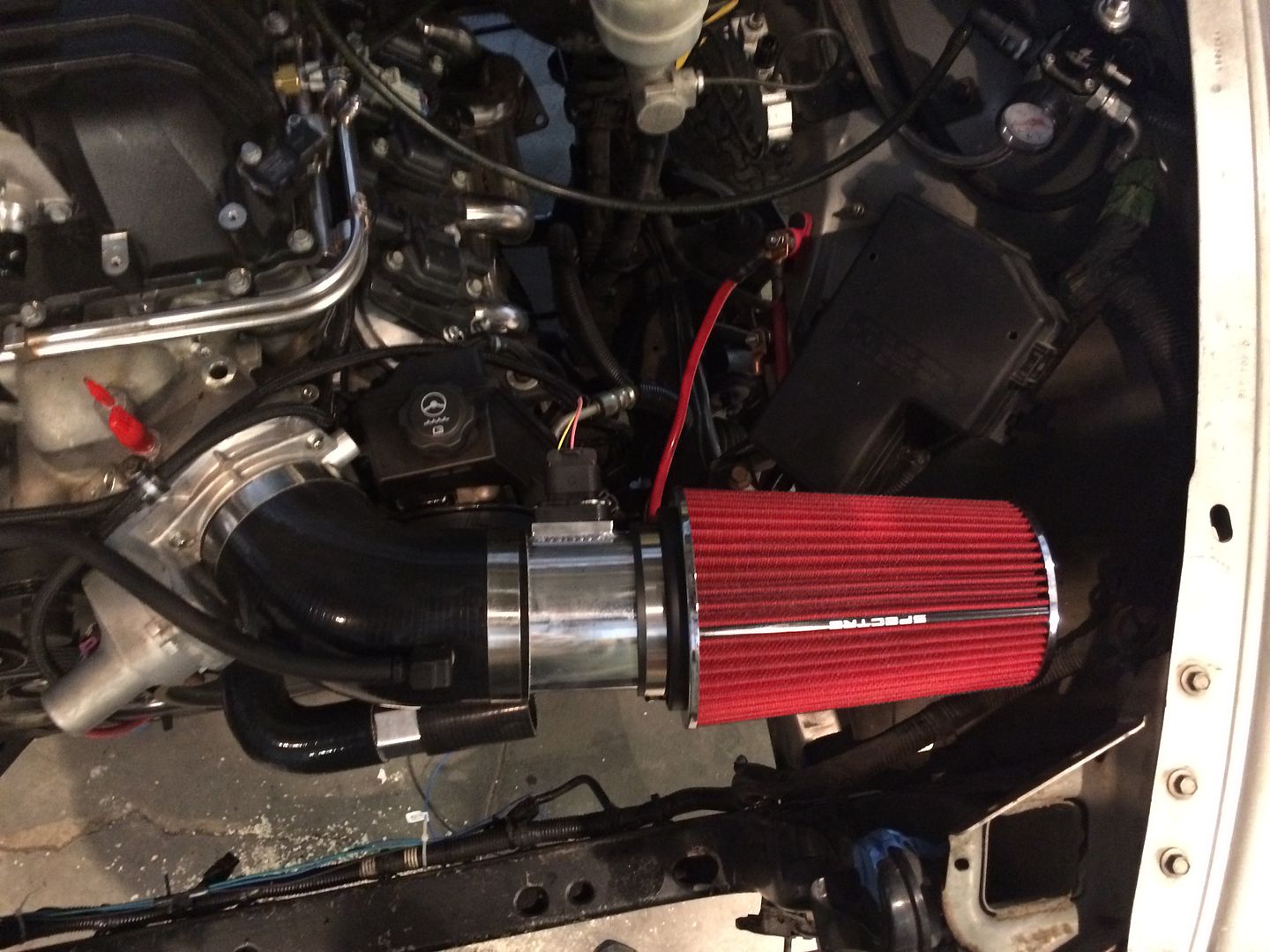 |
|
|
|
Post by casias on Jul 20, 2016 18:00:43 GMT -5
Ok, time for a much needed update. I have been working on the Durango, but heat has slowed me down a little. Also, I am doing stuff that takes a lot of time, with little to show for it. Here are some pictures. This is the top of the supercharger snout. It took me a few calls to get the right answer to the question "What are all these nipples for?". Turns out, the blue arrow is the stock location for the EVAP purge solenoid (I won't use that), the red arrow is vacuum port for the brake booster, the green circle is a vacuum nipple for some applications, sometimes capped of on others, the orange box is a second MAP sensor that reads vacuum pressure just behind the throttle body, but the ECU doesn't do anything with the information. Engineers might have planned something, but ditched the idea later. In my case, I will use the brake booster nipple, and plug the rest. 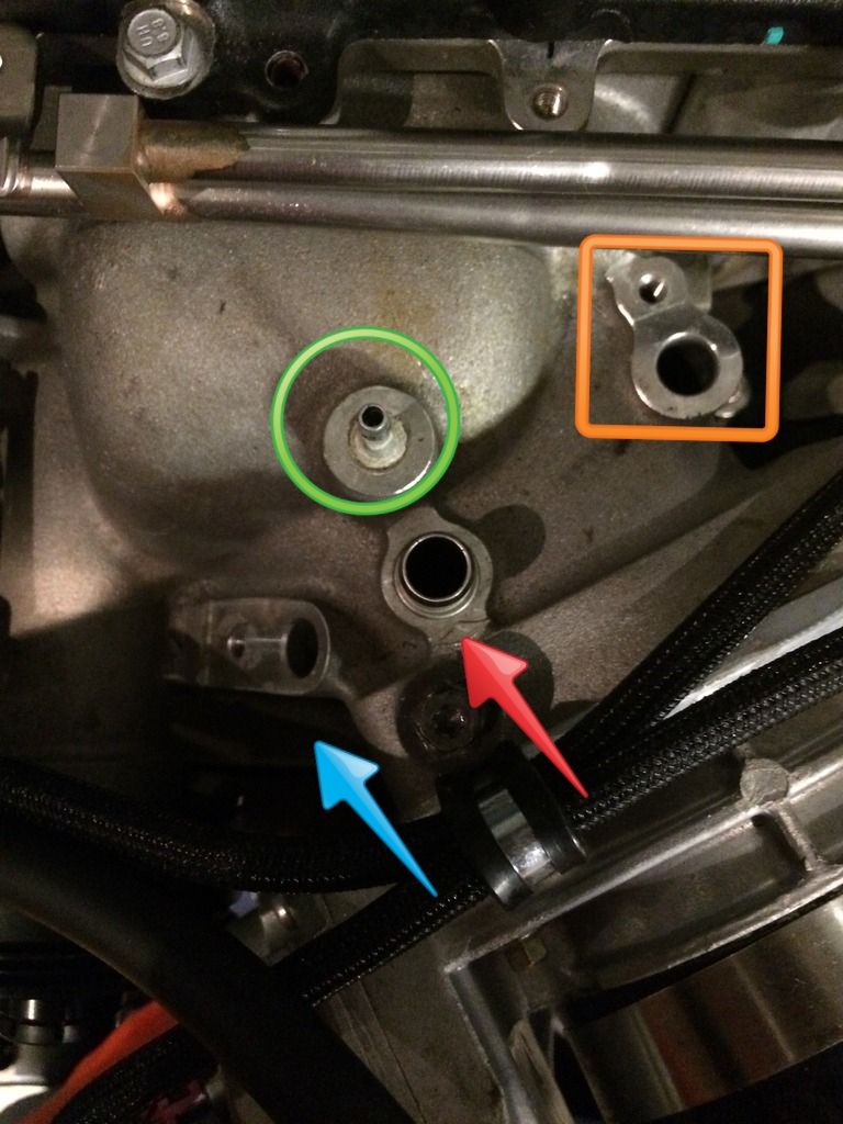 What do you do when you need to use and adapter very close to the radius? Open up the end. 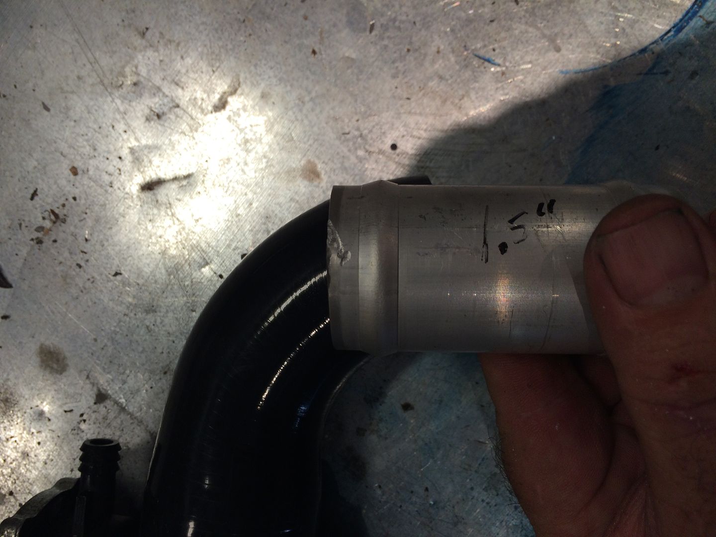 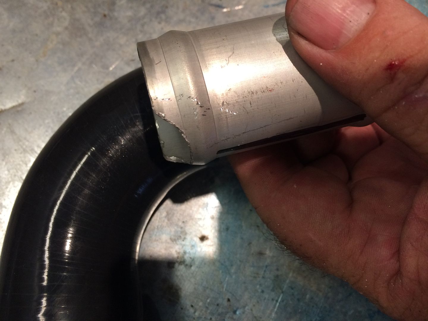 A radiator hose only a mother could love. 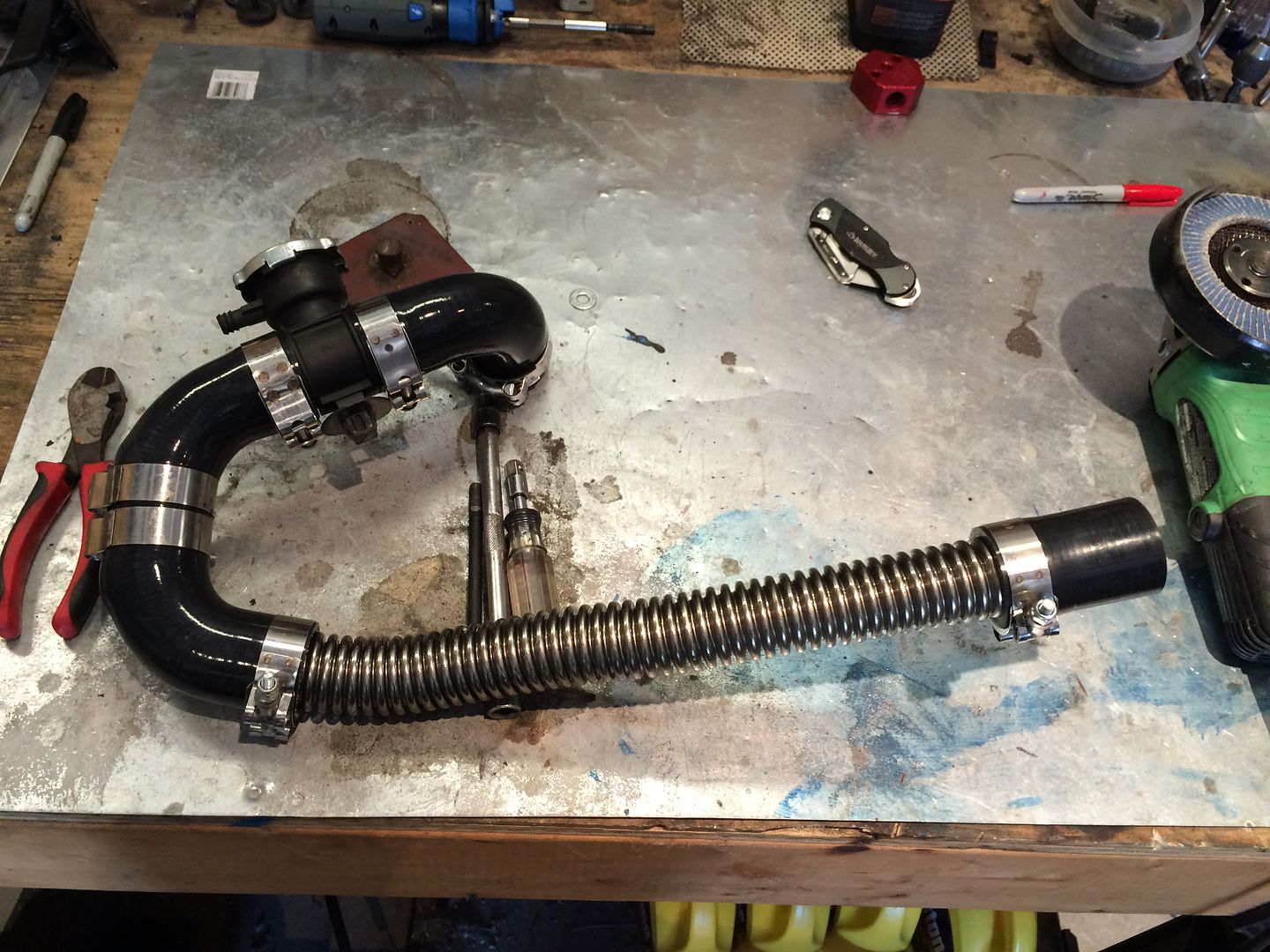 And what about that intercooler? Wanting to keep this 4X4 and not wanting a big intercooler in front of the radiator, I chose to use 2 Durango heater cores as the intercooler. They tucked up real nice behind the lower radiator support, and should be pretty well protected. I attached fans to each, which will run continuously. Not sure how this is going to work out, but some simple math tells me it will work fine. Only time will tell. 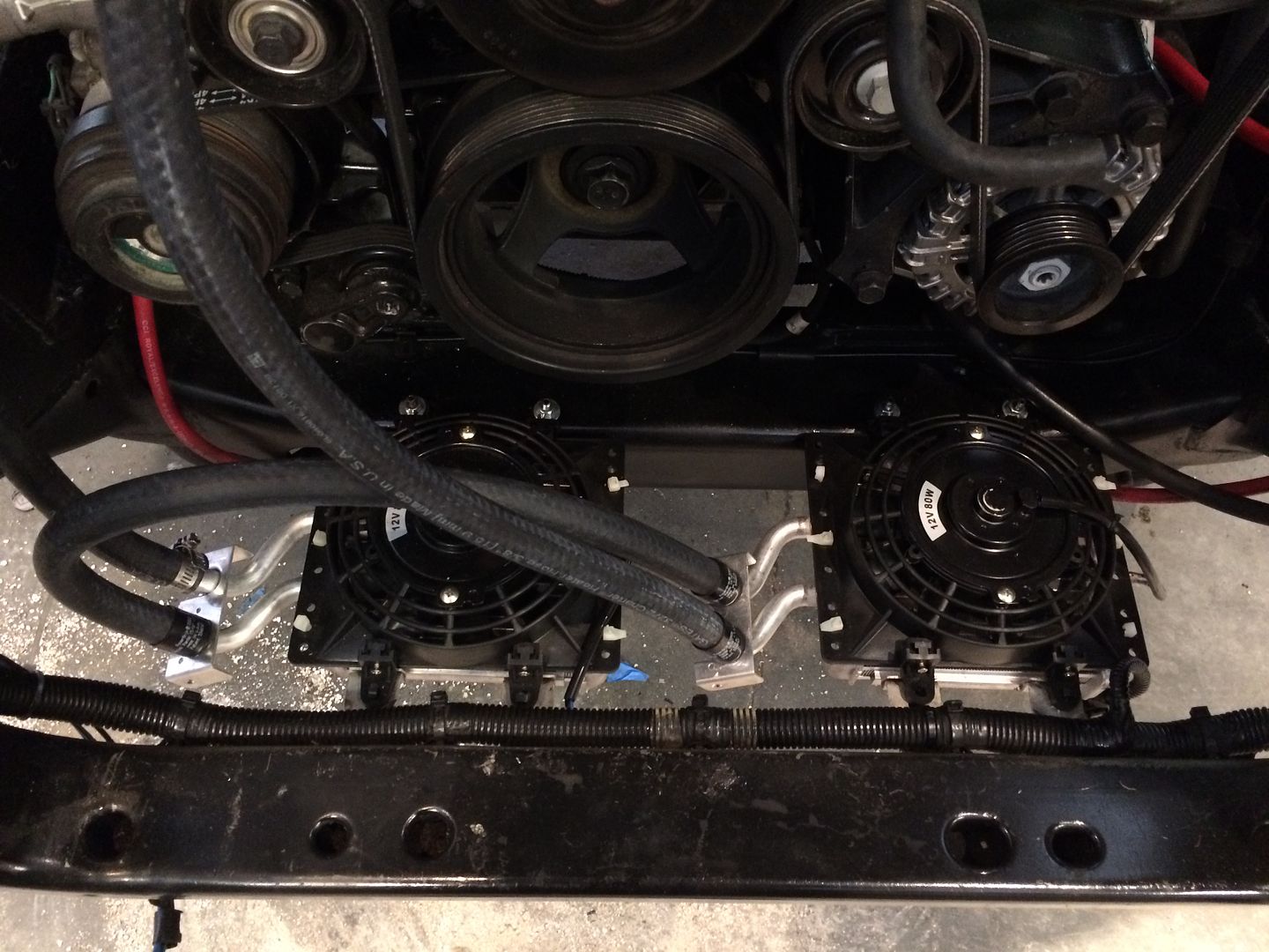 Gates Powergrip clamps make nice hose ends. 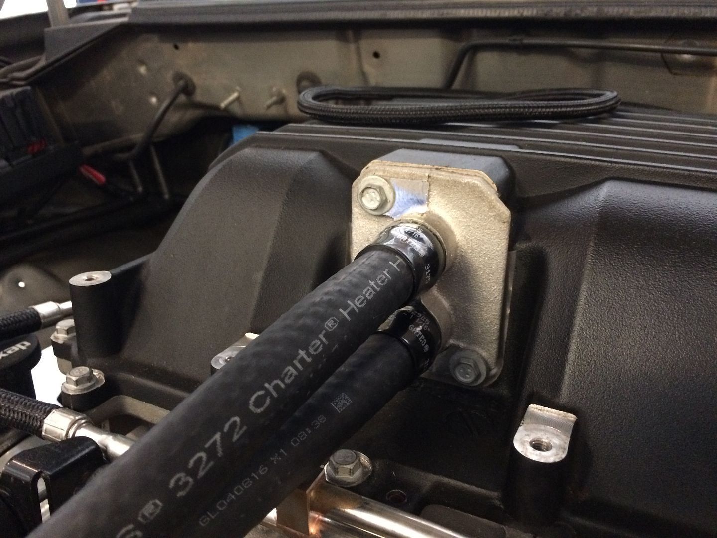 Pump is placed on a 1/2 piece of pipe welded to the frame on the passenger side. Hose exits through the front of the fender, into the fenderwell, then into the pump intake. 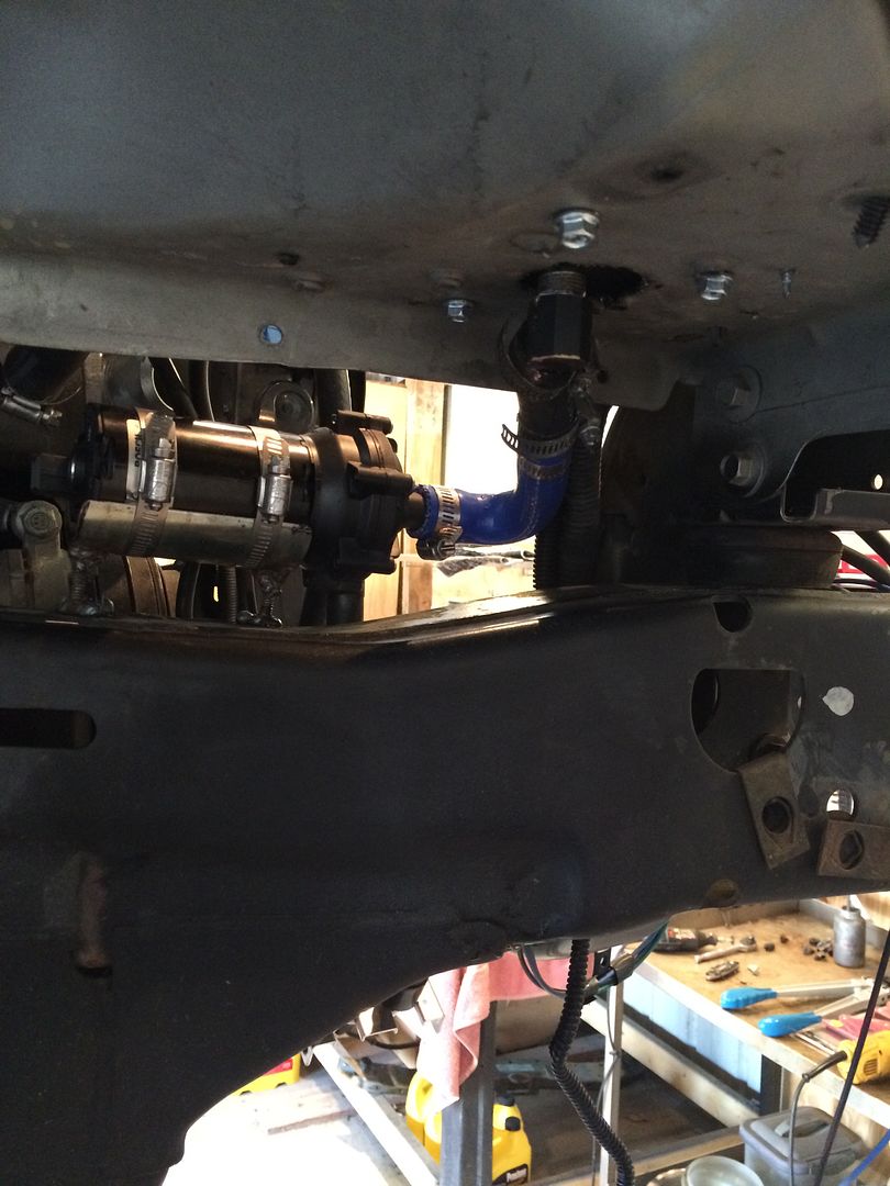 And now for the creative part of the intercooler setup. I started looking for a good reservoir for the system, and found 1/2 to 1 gallon aluminum running $80 to well over $200. So I called up my friends at Walmart, and they happened to have a 72 oz Bubba Keg for $15. Tap the bottom, tap the lid, put in a couple of fittings from Lowe's,and there you are. 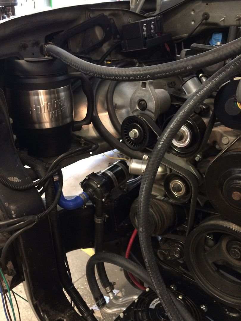 Final picture before the radiator goes in. 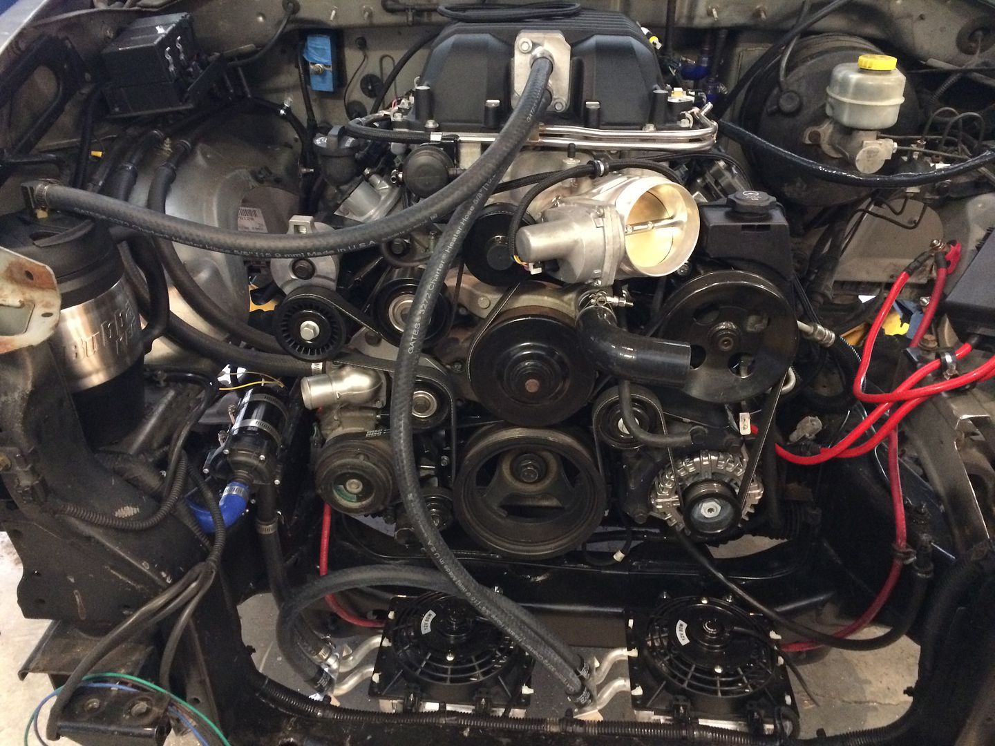 |
|
|
|
Post by casias on Jul 21, 2016 10:47:59 GMT -5
I found the pictures for the Bubba Keg modification. For the lid, I used a 1/2 MIP to 1/2 flare, and cut the flare nut so the fitting acts as a hybrid bulkhead fitting in this very thin lid. I don't know what I did with the pictures for the bottom, but I drilled a hole through, and put 1/2 x 2 inch pipe through, and sealed it with blue rtv. The keg is mounted on the flat part of the fender with 10 mm bolts drilled into the edge of the keg. If they start to get loose, I will probably just run some bolts right through the bottom, and seal it up with rtv just like the outlet nipple. Bottom of the keg tapped with pipe, and brass elbow. M10 bolts screwed into the edge to hold it on the fender. 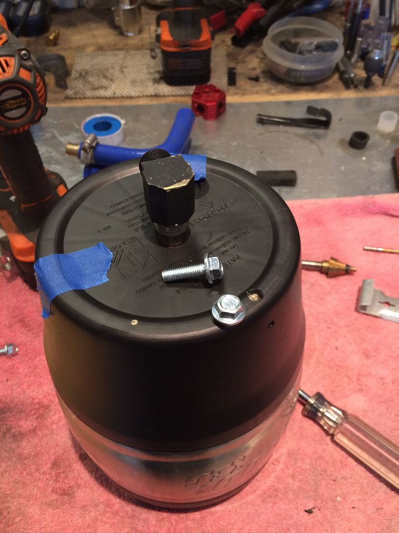 Pump mounted to 3 inch pipe cut in half, with bolts welded on to act as legs. Radiator clamps hold it in place, and make it easy to service if need be. 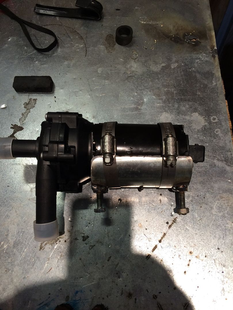 Brass elbows have a pretty small orifice. No big deal. Use a drill press and 1/2 inch drill bit and open them up. 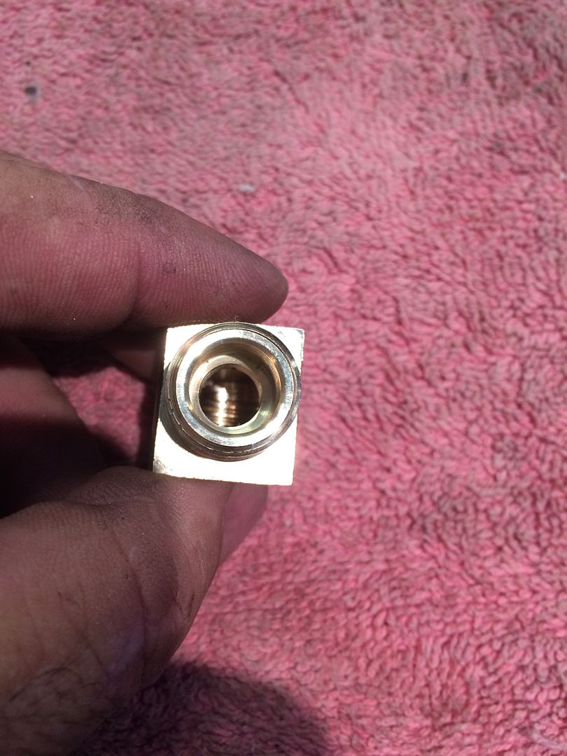 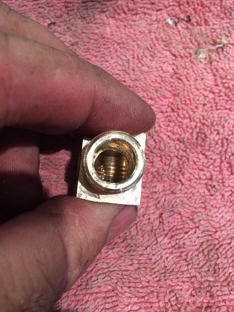 Final keg assembly. I painted the brass fittings black so they wouldn't stand out as much. 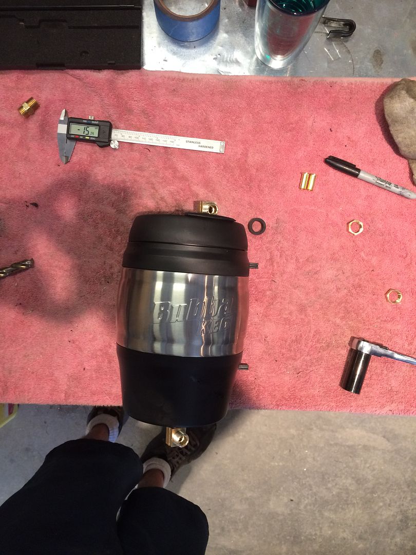 Here is how I cut the top off of a flare nut to make a bulkhead for the thin lid. The upper one is unmodified, the lower one has the nut cut, and is screwed all the way down. 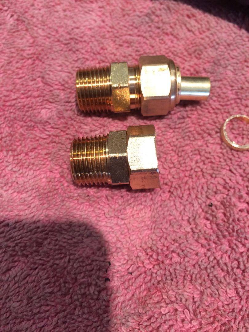 And here it is in the lid, with the cut side of the nut facing out. 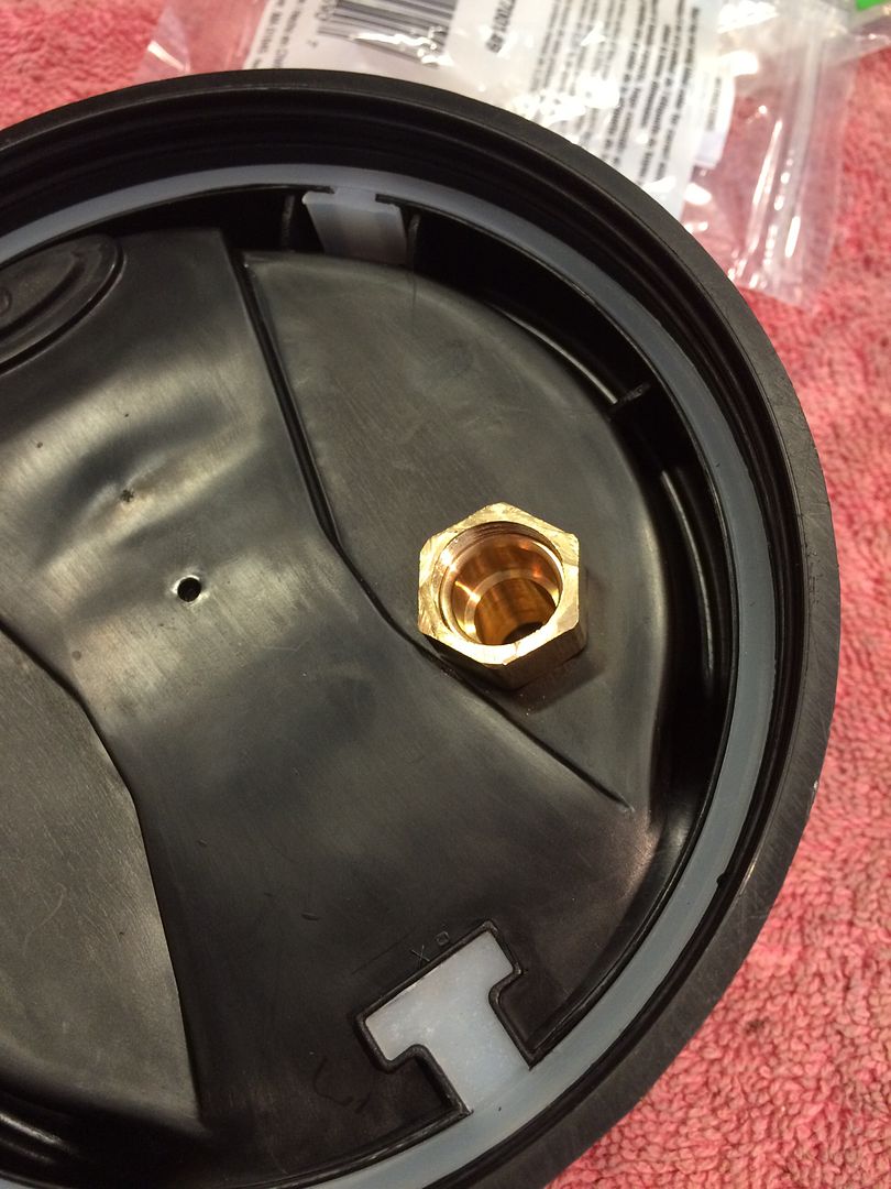 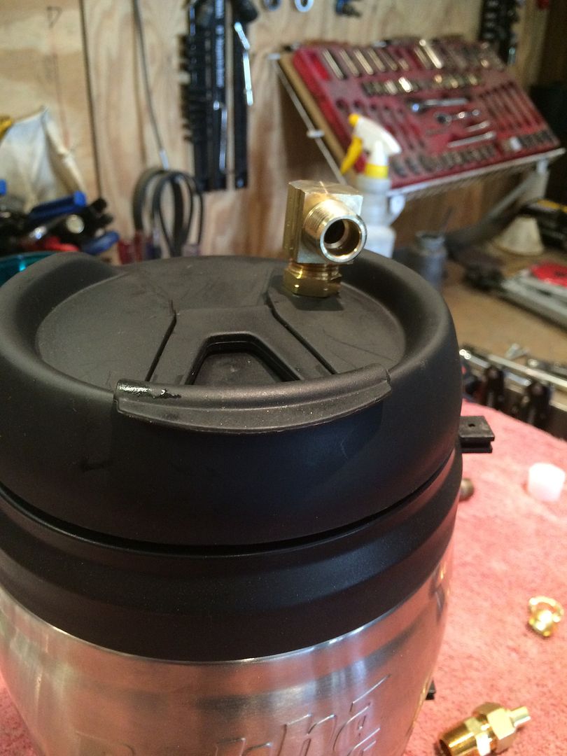 |
|
|
|
Post by casias on Jul 22, 2016 18:14:34 GMT -5
Ok. Engine bay is fully assembled. Now I just have to move into the cab for wiring, and accelerator pedal. It has to come off of the lift for that. I am too fat to squeeze under the dash with the door only half way open. HA! 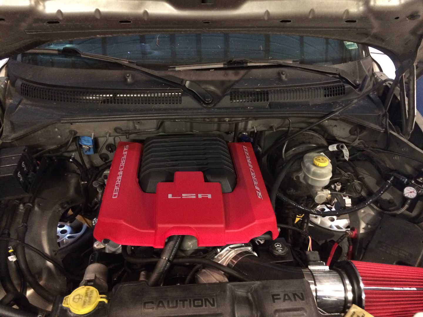 |
|
|
|
Post by sbatiste92 on Jul 23, 2016 13:30:48 GMT -5
That engine cover makes the whole engine bay scream badass
|
|
|
|
Post by casias on Jul 27, 2016 1:11:21 GMT -5
Finally to the pedal assembly. Using the new assembly that was sent with the wiring harness, I realized that the pivot point was much higher than the dakota pedal, which pivots at the middle. After "eyeballing" where I wanted the pedal to sit, I took some measurements and realized that I needed to mount the pedal about 4 inches higher than the firewall studs. I don't like a wimpy pedal, so i like to keep the original mounting studs, and make an adapter to fit. In this case, I used a piece of steel that came from a commercial shelving kit. My wife works for the county, and brings me tons of this leftover stuff from kits the maintenance guys assemble. Worked out real nice in this case. Original pedal location with pivot just below the attachment points (Sorry about the picture quality. My phone didn't like being under the dash on a sticky 94 degree day any more than I did). 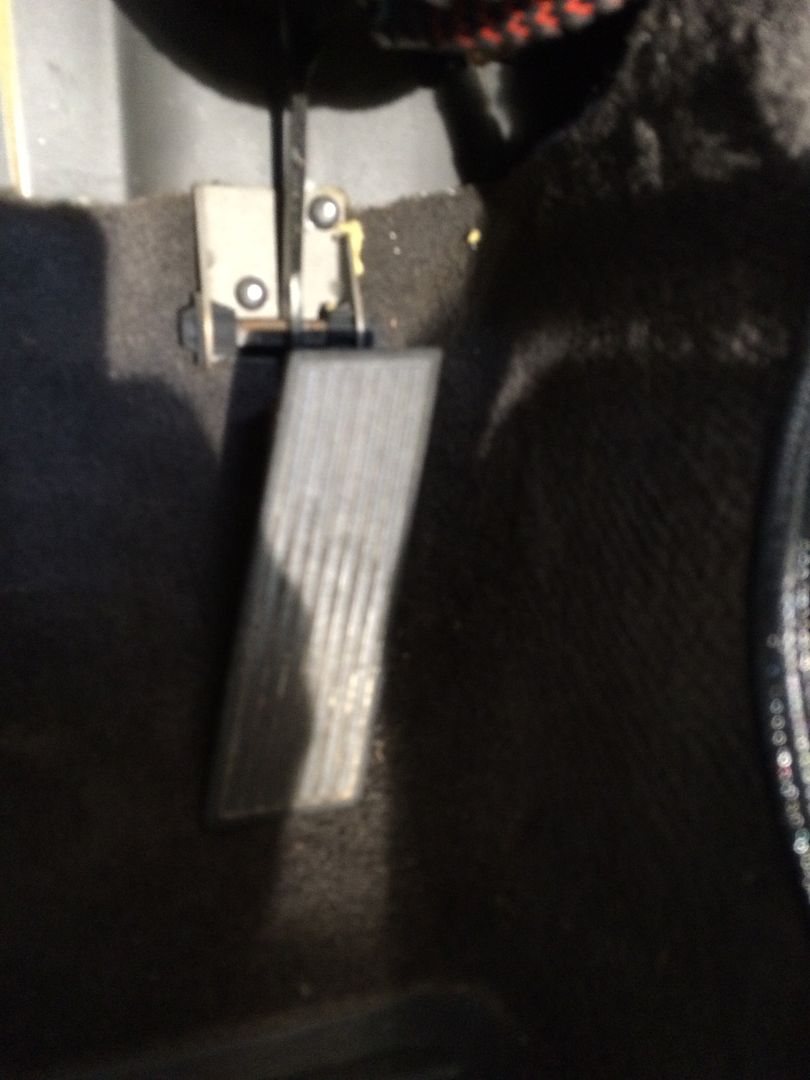 Remove the old accelerator cable. Probably should have done this when the engine was out. 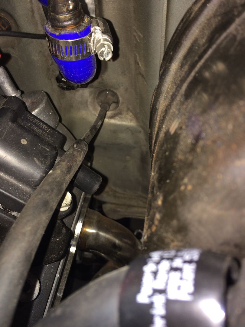 Scrap steel used for plate. I left the flange on to give it rigidity. 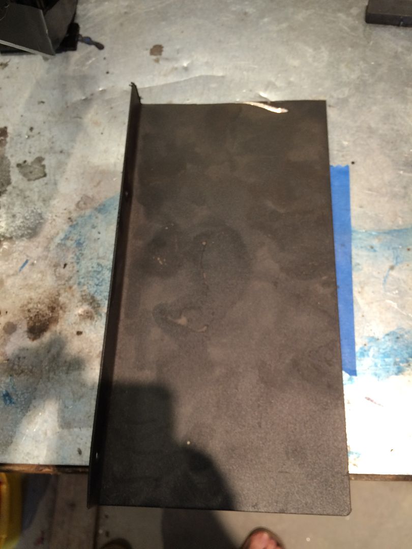 Cut to size and holes added. 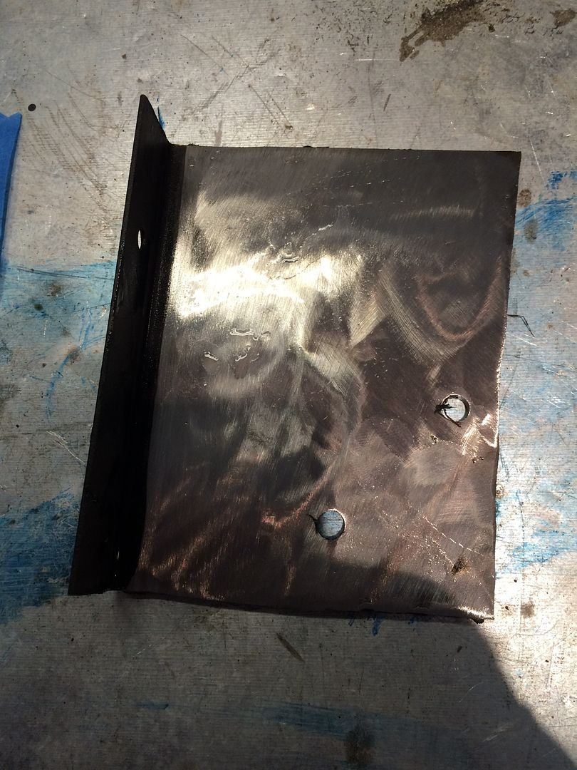 Pedal assembly welded into place. 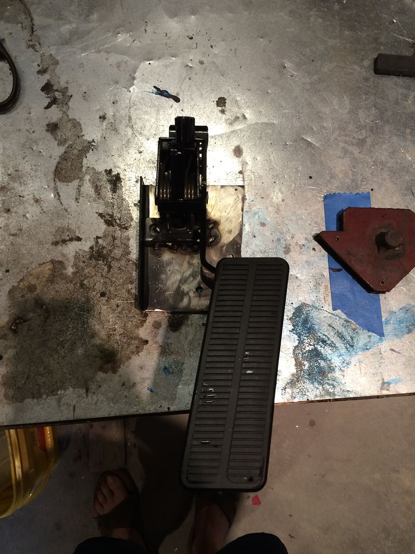 And installed. My goals were 1) pedal in original location 2) nuts easy to reach 3) simple, rigid bracket. Accomplished. 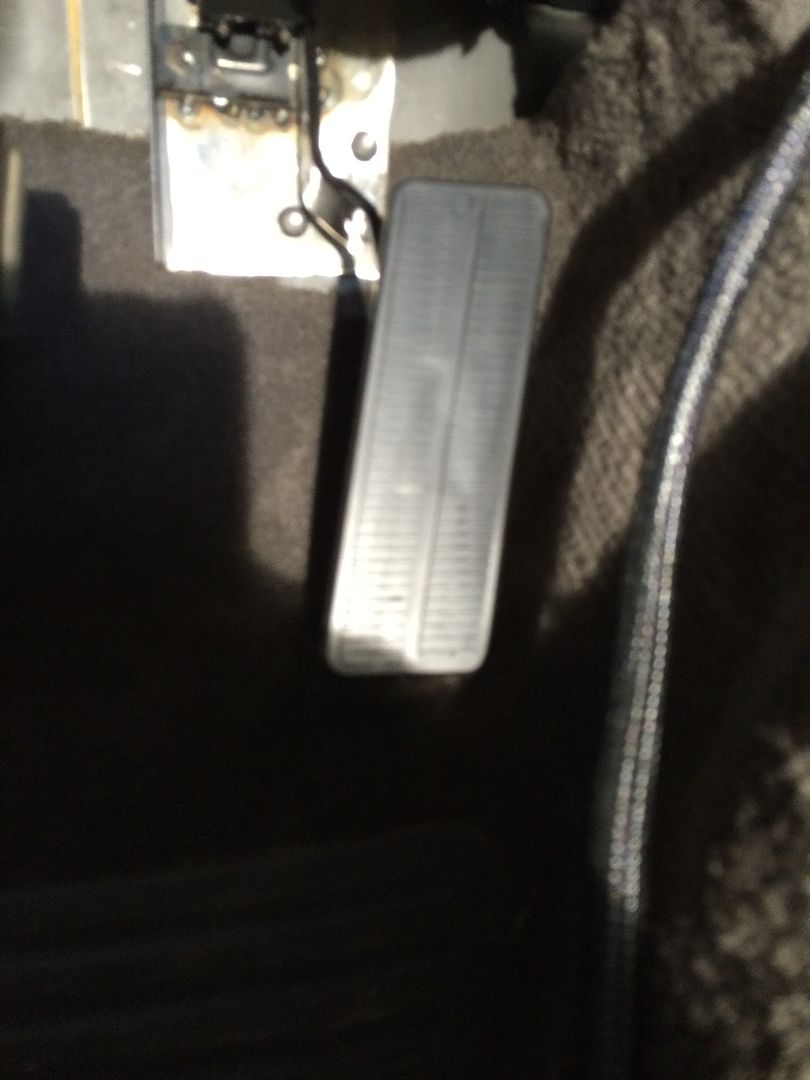 |
|
|
|
Post by casias on Aug 3, 2016 8:24:52 GMT -5
Check out the video of the first start up. Runs kind of OK on a completely wrong base-tune. Right now, it has open header pipes that are about 2 feet long with 02 sensor bungs welded in. So it is pretty throaty at the moment. www.youtube.com/watch?v=AzyimKwx5Eo |
|
|
|
Post by sbatiste92 on Aug 4, 2016 1:36:28 GMT -5
You've done an incredible job on this build and provided some really great information along the way that will certainly atleast help me finish my Durango if it doesn't get out to anyone else. Awesome to see that it runs. Can't wait to see some more videos of you getting a chance to drive it, and maybe some track videos in the future
|
|